A 450A DC contactor should be selected against continuous and peak current, installed thermal conditions, DC switching duty and the separate coil supply. First decide whether 450A is a sustained requirement or a brief event. Then verify the candidate’s supported conductors, ambient conditions, opening capability, closing event and protective coordination. A higher current label does not guarantee a cooler joint, a suitable DC breaking rating or an interchangeable replacement. Approval needs the exact ordering code and evidence for the actual equipment duty.
This guide emphasizes the thermal evidence needed for a sustained high-current battery or industrial DC connection. It also shows how to keep heat calculations, switching limits and procurement decisions separate, so a plausible temperature estimate does not become an unsupported product rating.
Describe the highest thermal demand
Provide current over time, not only an average. Record sustained operation, short peaks, idle intervals and switching frequency. Identify the operating point at which both current and enclosure temperature are most demanding. If cooling can stop while the circuit remains energized, include that state in the equipment review.
Clarify whether the 450A value is a load requirement, a supplier’s continuous carrying label or a short-time capability. For a short-time value, request duration, starting temperature, repetition and recovery conditions. A peak-current allowance cannot be treated as continuous duty by omitting its time limit.
Use the actual conductor configuration and cabinet arrangement. A supplier test with specified busbars and ambient conditions may not predict a smaller cable connection in a crowded sealed enclosure. Ask what installation assumptions support the rating and which changes need separate review.
Understand why small resistance changes matter
For a defined resistive path, power loss is P = I²R, with current I in amperes, resistance R in ohms and loss P in watts. As an arithmetic illustration only, 450A through 0.0001 ohm produces 20.25W: 450 × 450 × 0.0001. Through 0.0002 ohm, the same calculation gives 40.5W.
These values are not measurements or specifications of any Sayoon contactor. The example shows why connection resistance matters. The path used in a real calculation must be clearly defined and measured or supported by documentation. Temperature, current distribution and external joints can affect that path.
The calculated watts do not establish a temperature rise. Heat transfer, conductor geometry, enclosure airflow and nearby components determine how loss affects temperature. Use the calculation to identify what needs evidence, then verify installed thermal behavior against approved limits.
Collect the evidence needed for a 450A review
| Review field | Equipment information | Evidence to request |
|---|---|---|
| 450A duty | Sustained load or timed peak | Conditions and duration of the supported carrying value |
| Resistance estimate | Clearly defined measured or documented path | Traceable input; hypothetical examples do not qualify a product |
| Thermal result | Actual enclosure, conductors and current profile | Installed temperatures against approved limits |
| Main closure | Inrush and restart sequence | Making evidence and permitted repetition |
| Main opening | DC voltage, current and current direction | Breaking qualification for the assigned event |
| Fault protection | Available source current and clearing device | Documented coordination and supported contactor role |
The table distinguishes a calculation input from a qualification result. The arithmetic example above can support a thermal discussion, but it cannot authorize carrying or interrupting 450A in an unspecified circuit. Each candidate needs evidence under the conditions attached to its rating.
Check joints, hardware and mechanical loading
Review lug or busbar material, contact surfaces, connection stack and approved fastening hardware. Follow the manufacturer’s drawing for washers, torque and terminal loading. Do not substitute a universal torque value from another frame or product series.
A rigid busbar can transmit assembly misalignment or thermal expansion to the contactor terminals. A heavy cable can impose weight and bending force. Provide appropriate support and confirm permitted loading. The mechanical connection is part of the electrical installation, not an unrelated detail added after current selection.
When a terminal runs hotter than expected, compare current, connection conditions and measurement locations with the baseline. Investigate the cause under the approved procedure. More torque, extra washers or an unapproved coating can change the joint and should not be adopted as improvised remedies.
Keep the making event independent of thermal carrying
A contactor can have adequate steady thermal capacity yet encounter an unsuitable closing event. For an inverter or DC-link capacitor, document initial voltage difference, capacitance and precharge completion. For a motor circuit, document starting and stalled conditions and the control sequence.
The capacitor field and charge explanation provides background for the charging event. It does not set contactor making limits. Require product evidence for the circuit conditions actually present when the contacts close.
Define failed-start and restart behavior. Repeated automatic closure into an unresolved inrush condition can create cumulative stress even when normal running current is below the carry label. A purchasing specification should state permitted repetition and abnormal-event handling rather than relying on successful steady operation alone.
Exclude AC-load and coil-only search matches
A search result combining 450A with an AC/DC coil description may concern an AC main-circuit contactor. The coil supply does not establish DC load-switching capability. Likewise, an AC-1 or AC-3 current listing cannot be adopted as a DC breaking rating. Read the main-circuit rating and load category in the actual product document before including such a candidate in the comparison.
Require a separate DC opening qualification
Write maximum operating voltage, current at opening, circuit characteristics, current direction and operation frequency. A contactor’s carrying label is not its breaking rating. A product intended to open after current reduction needs a defined and verified reduction sequence.
For battery charging or regenerative equipment, trace reverse current and confirm whether opening in that direction is permitted. Closed contacts conducting current both ways do not establish bidirectional arc interruption. Preserve terminal orientation and exact product variant in the installation record.
The IEC 60947-4-1 record describes the relevant contactor standard scope. Check actual product ratings and supporting documents rather than turning a reference to that standard into a general 450A switching claim.
Match the coil and control response
Specify AC or DC coil supply, voltage range at pickup and holding, driver capability and permitted supply variation. Record internal suppression and economizer requirements. The main-path current says nothing about which coil voltage should be ordered.
Include brownout, lost control power and restored supply in the sequence. Confirm what state is expected and what feedback establishes it. Where timing matters, compare the controller command, coil response and main-path feedback rather than assuming they occur simultaneously.
Coordinate protection and qualify the installed assembly
Identify available fault current and the device assigned to clear it. Ask for the contactor’s supported behavior while that protection operates. A routine high-current connection should not be assigned fault interruption merely because its carrying label is large.
Define an installed validation covering the demanding current profile, thermal environment, conductors, coil range and switching sequence. Record the arrangement and measurement method so results can be reproduced. Compare body and terminal temperatures with documented limits, including limits of nearby components.
For servicing covered by the regulation, OSHA 1910.333 addresses de-energization and verification. Testing and inspection must use appropriate procedures and qualified personnel. An ordinary opening command does not prove absence of stored energy or other sources.
Make the RFQ and spare-part record specific
Send the supplier current-time data, voltage range, thermal conditions, connection drawing, making and breaking events, protection and control requirements. Ask for the exact supported variant and unresolved limitations. Request installation instructions before finalizing conductor and mounting details.
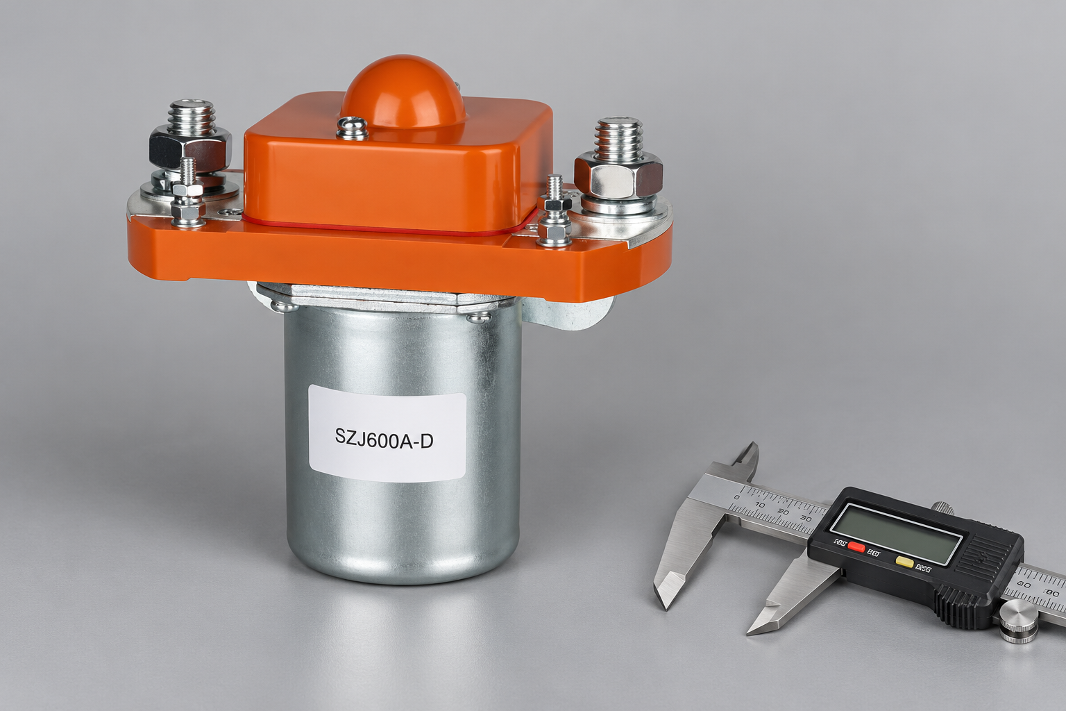
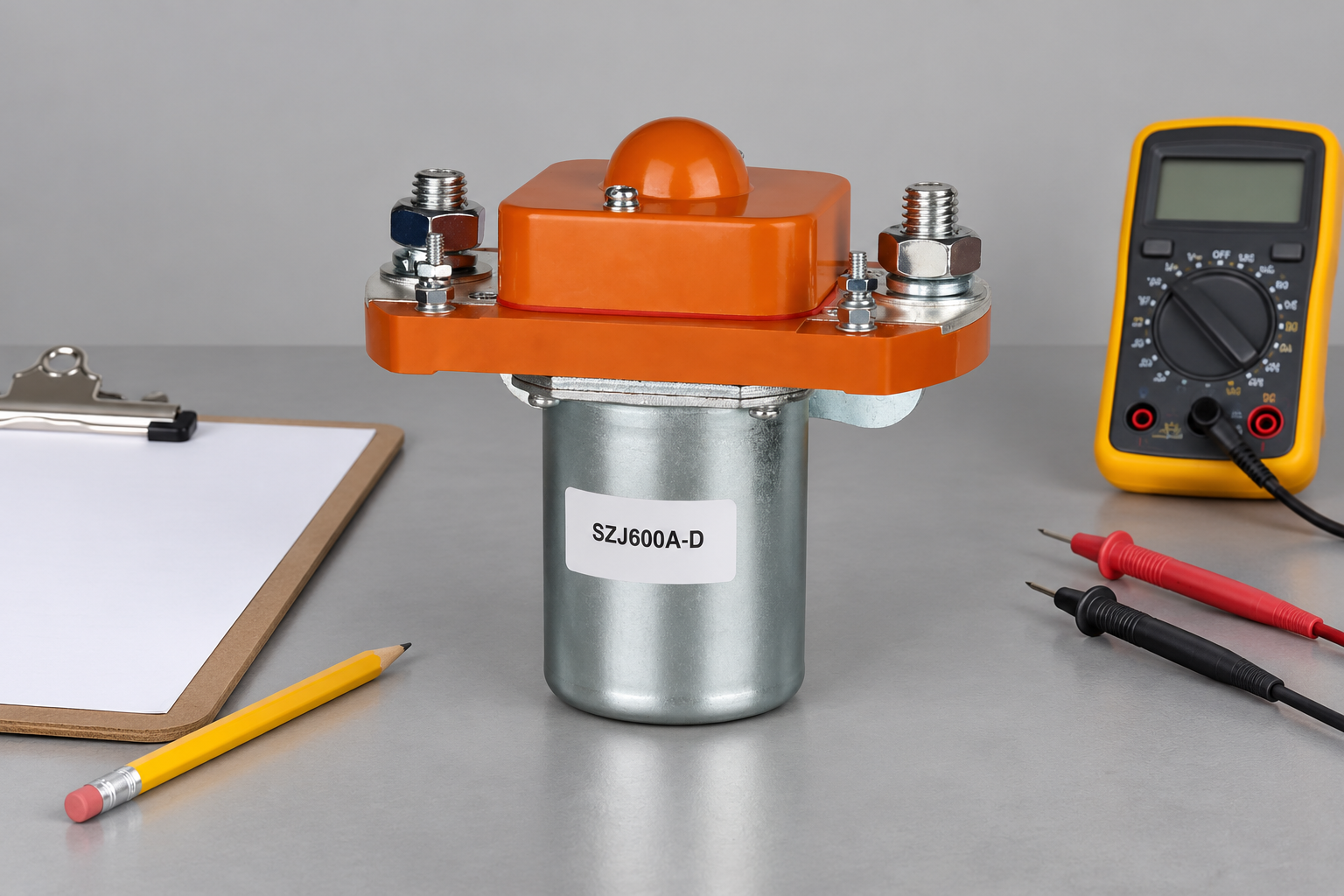
Review the SZJ600A-D Normally Open DC Contactor product page for an external construction reference. This conventional construction example is not a qualified candidate for the article’s stated duty; obtain an appropriately rated variant and product-specific evidence from Sayoon. The picture demonstrates external construction and is not a tested 450A installation. Use the OEM specification checklist to organize the evidence. For focused supporting checks, review busbar connection design, và temperature derating review. Keep the approved drawing revision, duty evidence and installed thermal result with the bill of materials. A substitute should satisfy the same recorded requirements, including coil and protection conditions that a visual comparison would miss.
Make thermal comparisons use the same measurement boundary
When comparing two candidates, use equivalent current, conductor geometry, surrounding temperature, mounting and measurement locations. A lower voltage-drop figure measured on one terminal arrangement cannot be compared directly with a result that includes additional cable joints. Label the measured path in each record.
Record both a baseline and the allowed acceptance criterion from the equipment or supplier documents. If the installed temperature exceeds that criterion, investigate load, connections, cooling and product suitability before accepting a larger current label as the solution. The replacement decision should be supported by an actual comparable test or documented qualification, not merely the arithmetic illustration in this guide.
Watch the basic contactor operating principle
Electrician U explains the electromagnetic contactor mechanism in this educational video. It supports the operating principle only; it does not demonstrate the selected model’s DC ratings, qualify this application or replace product documentation.

Watch the Electrician U contactor explanation on YouTube.
Các câu hỏi thường gặp
Is 450A always a continuous rating?
No. A listing may describe continuous carrying or short-time capability. Confirm the conditions, duration, conductors and temperature for the exact variant.
Does the power-loss example specify Sayoon contact resistance?
No. The resistance values are hypothetical arithmetic inputs. Use product documentation or a defined approved measurement for actual equipment assessment.
Can calculated watts predict terminal temperature directly?
No. The installed heat-transfer conditions and surrounding components also matter. Validate temperature against documented limits.
Does choosing a 600A model automatically solve a 450A application?
No. Verify the actual installation, voltage, making and breaking duty, coil, mounting and fault coordination. A headline current difference is insufficient.





