Câu trả lời nhanh: An EV contactor feedback signal is plausible only when the command, coil current, auxiliary contact, and measured high-voltage response agree inside defined timing windows. An auxiliary contact alone cannot prove that the main current path is healthy. The battery-management system should diagnose stuck-open, welded, delayed, back-fed, and wiring faults by comparing independent evidence and latching the first mismatch before any retry.
This engineering guide turns the topic into a reviewable sequence for battery-pack, BMS, test, sourcing, and service teams. It uses the real product family as a reference while keeping every rating and safety decision tied to the final application and current manufacturer documentation.
Decision map
| Operating state | Expected evidence | Engineering focus |
|---|---|---|
| Open command | Auxiliary open and load-side bus decays | Welded contact, back-feed, slow release, feedback wiring |
| Close command | Coil current appears, auxiliary closes, bus follows precharge | Open coil, weak supply, stuck mechanism, blown fuse |
| No command | No coil current and open-state feedback | Driver leakage, short-to-battery, wrong polarity |
| Fault recovery | No automatic reclose until state is proven safe | Stored energy, intermittent harness, cleared evidence |
Product reference and application boundary
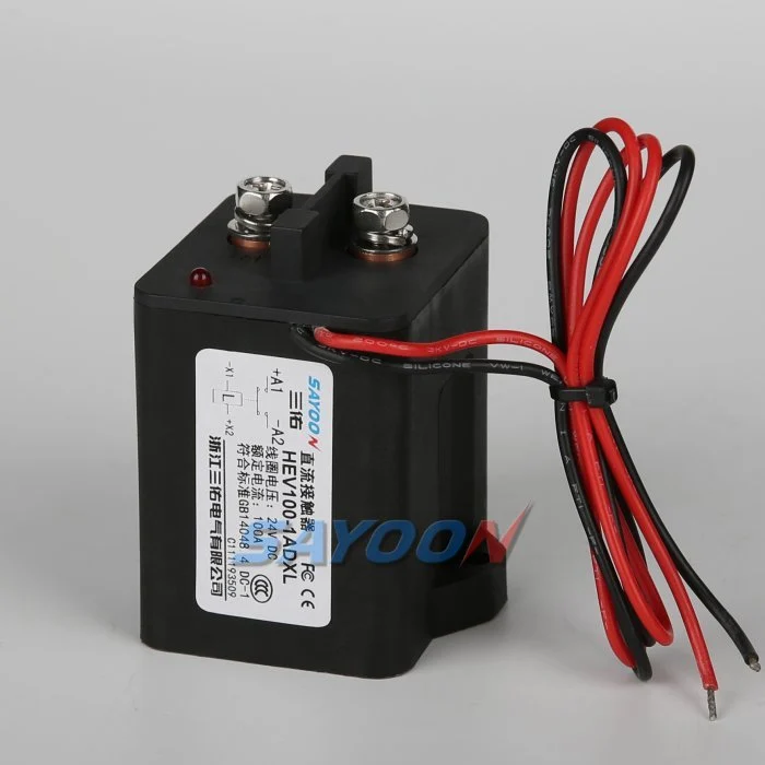
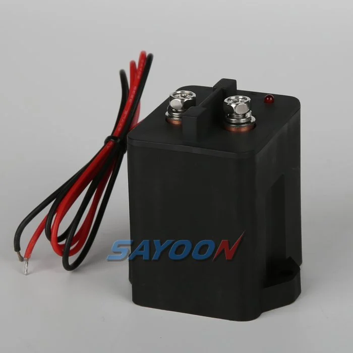
The HEV100 high-voltage sealed DC contactor shown here is a real Sayoon product reference. Review the high-voltage DC contactor range for adjacent current classes. The image and family name do not establish approval for a particular vehicle. The final part number, coil option, drawing, electrical duty, insulation, environment, life, and protection coordination must be reviewed together.
What plausibility means in an EV contactor circuit
Plausibility is a comparison between signals that should describe the same physical event. The controller issues a close or open command. The driver produces coil current. The mechanism moves and changes an auxiliary contact. The main contacts then change the load-side voltage. Each signal observes a different layer, so agreement is stronger evidence than any single input. A disagreement is not automatically a failed contactor; it is a prompt to identify which layer no longer matches the electrical state.
Define expected combinations for key-off, precharge, drive-ready, charging, service, crash, and fault shutdown. Record the allowable transition time and the action for each mismatch. Avoid a single generic “contactor fault,” because a driver short, a broken feedback wire, and a welded main contact require different service actions.
Command and coil-current checks
A command bit proves only that software requested an action. Confirm that the low-voltage supply remains inside the approved range during pull-in and that the driver delivered the expected current waveform. A high-side or low-side switch may report open-load, short-to-ground, over-temperature, or current-limit status. Store those flags with the command timestamp. If the command is present but current is absent, investigate the supply, driver, connector, winding, and interlock permission before replacing the contactor.
Economized coils may show a short pull-in peak followed by lower hold current. The exact waveform depends on the coil option and suppression. Use a model-specific envelope rather than a universal threshold. An unexpectedly long current tail after an open command can delay mechanical release and make a healthy auxiliary contact appear late.
Auxiliary feedback limitations
An auxiliary contact normally follows the armature position, but it does not measure resistance through the main terminals. The main contacts can be eroded, partially closed, or welded while the feedback circuit reports a different state. The feedback input can also fail because of contact bounce, an overloaded wetting current, corrosion, a broken wire, or an incorrect normally-open versus normally-closed configuration.
Debounce should reject brief bounce without masking a real interlock or release event. Define separate thresholds for initial transition, stable state, and implausible toggling. Test open-circuit and short-to-supply faults at the connector so the software can distinguish a wiring fault from a genuine mechanism position.
Use bus voltage as independent evidence
Measure both pack-side and load-side voltage. During precharge, the load-side bus should rise along the predicted path before the main contactor closes. During opening, it should decay through the approved discharge path. If the auxiliary says open but the bus remains near pack voltage, suspect welded contacts, a bypass, or an external back-feed. If the auxiliary says closed but the bus does not rise, suspect a stuck-open main path, fuse, busbar, or measurement fault.
The threshold and timeout depend on capacitance, resistance, leakage, battery voltage, measurement error, and connected converters. Capture the voltage curve instead of checking one sample. Verify that a charger or DC-DC converter cannot keep the bus energized and create a false weld diagnosis.
Timing windows and state-machine design
Measure pull-in, bounce, settling, release, and discharge at the minimum and maximum coil supply, cold and hot conditions, and the longest approved harness. Set software windows from validated distributions with documented margin. A very short timeout can create nuisance faults; an excessive timeout can leave hazardous energy connected longer than the safety concept permits.
Use explicit states such as open-verified, precharging, close-pending, closed-verified, open-pending, discharge-pending, and fault-latched. Entry and exit conditions should reference measured evidence. Preserve the first-fault snapshot even if a later signal changes, because automatic retries can hide intermittent wiring and marginal pull-in.
Fault signatures and service decisions
A stuck-open event commonly shows a valid close command and driver output but no auxiliary transition or expected bus rise. A welded event commonly shows an open command with persistent bus voltage, with or without closed auxiliary feedback. A feedback-wire open can show an impossible input while coil current and bus response remain normal. A back-feed can keep the bus high with both main contactors mechanically open.
When the system cannot prove the open state, inhibit torque and charging, stop retries, discharge through the approved path, and require the vehicle service procedure. Do not bridge feedback pins or force the coil on an energized pack. The weld-detection guide explains the voltage-decay checks that complement this article.
Commissioning test sequence
Begin with the high-voltage system isolated. Confirm the complete part number, coil polarity, auxiliary contact type, connector pinout, and feedback input current. Exercise the coil with a current-limited supply while recording command, voltage, current, and auxiliary timing. Then perform a controlled precharge and opening test with authorized equipment, recording pack and load-side voltage on the same time base.
Inject one fault at a time using approved simulators: open feedback wire, shorted feedback input, low coil voltage, missing coil, delayed transition, and a modeled persistent bus voltage. Verify the diagnostic code, latched data, inhibited reclose, and service message. Repeat at temperature and supply boundaries.
RFQ and design-review checklist
Provide battery voltage range, continuous and peak current, coil voltage, driver topology, suppression, auxiliary contact logic and wetting current, harness length, precharge and discharge circuits, bus-sense accuracy, timing requirements, fault strategy, environment, and target cycles. Request the exact drawing and validated timing data for the selected coil option.
The HEV100 shown here is a product reference, not automatic approval for every EV pack. Match the model to the full electrical, thermal, insulation, and diagnostic requirements.
Acceptance record
Create one controlled record containing the complete part number, drawing revision, coil option, terminal functions, voltage range, current waveform, switching state, precharge and discharge details, driver and suppression, auxiliary logic, HVIL state, protection, ambient and enclosure temperatures, mounting orientation, conductor and busbar details, instrument locations, calibration status, software version, and pass/fail limits. Separate measured values from catalogue values and mark missing evidence as an open action rather than inserting a typical value.
Test at the boundaries that matter: low and high coil supply, cold and hot conditions, longest approved harness, repeated cycles, and the abnormal state named in the safety concept. Capture command, coil voltage and current, auxiliary feedback, pack voltage, load-side voltage, and fault flags on one time base. Stop automatic retries after an unexplained mismatch, isolate stored energy, and preserve first-fault evidence. Photograph the setup and terminal layout, identify every probe point, record the production-intent harness and busbar, and explain why each threshold is safe. Repeat a representative sample after thermal stabilization and after the planned endurance block. Include the operator, test date, sample identity, and every deviation from the production assembly. A later successful cycle must not erase an earlier fault. These records allow a replacement sample, supplier revision, firmware update, or harness change to be compared against the same approved baseline.
Related Sayoon guides
Sử dụng Hướng dẫn lựa chọn khởi động từ DC (contactor DC), quy trình kiểm tra khởi động từ an toàn, và opening and closing time guide for complementary decisions. The EV contactor weld-detection guide provides the related voltage-decay method.
Video giáo dục
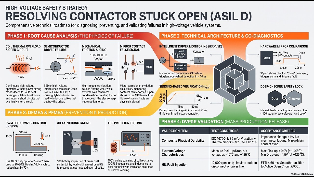
C05 EV Contactor Stuck Open by Roger Chen provides visual background related to this engineering review. It does not replace the written requirements, product data, or vehicle safety procedure.
Xem video giáo dục trên YouTube.
Các câu hỏi thường gặp
What is the most important check for ev contactor feedback signal?
Start with the maximum voltage and real switching waveform, then verify the exact contactor data, control sequence, installation, and fault behavior together.
Can an auxiliary contact prove that the main contacts are healthy?
No. Auxiliary feedback reports mechanism position within its limits. Use bus voltage, timing, coil current, and the circuit state as independent evidence.
Can a nominal current rating be used as the complete selection rule?
No. Continuous current, make current, break current, voltage, temperature, polarity, life, insulation, and protection coordination are separate conditions.
What information should be sent with an RFQ?
Send voltage and current waveforms, switching sequence, environment, coil and driver details, feedback logic, protection, mounting, life target, and required test evidence.
Các tài liệu tham khảo có thẩm quyền
- Texas Instruments, Driving High-Voltage Contactors in EV and HEVs
- Texas Instruments, isolated relay-welding detection
- Google Patents, contactor feedback and precharge/discharge circuit
Use the edition and requirements adopted by the vehicle program. Standards and supplier data may change, and the responsible engineering team must confirm the final design.





