When comparing a high side vs low side contactor driver, the difference is where the electronic switch sits in the coil supply circuit. A high-side driver switches the positive feed while the coil return remains connected; a low-side driver switches the return while the coil positive feed remains connected. Neither arrangement changes the contactor’s main DC contacts. Choose the topology from the control output, grounding and fault-detection requirements, coil polarity, and permitted turn-off transient. Then verify the complete circuit using the exact coil and driver documentation. A schematic copied from a different contactor is not sufficient evidence of compatibility.
Draw the coil circuit before choosing a driver
Begin with four items on a drawing: the coil supply, the two actual coil terminals, the controlled switch, and the energy-discharge path when the switch opens. Add the return and chassis connections, protective device, interface connector, and any built-in economizer or suppressor. This small drawing prevents a common mistake: discussing high-side and low-side switching as if they describe the contactor’s power poles. They do not. The power poles can interrupt a much higher-voltage DC circuit, while the control topology concerns the lower-power coil circuit only.
In a conventional low-side circuit, supply positive goes to the coil and an N-channel transistor or similar device connects the other coil terminal to return. In a high-side circuit, an approved output connects supply positive to the coil; the other coil terminal has a defined return. A sourcing PLC output commonly behaves as a high-side switch, while a sinking PLC output commonly behaves as a low-side switch. The words “sourcing” and “sinking” belong to the PLC output specification, however: they must not be guessed from wire colors or terminal names. See our PLC-to-contactor coil guide for the separate question of whether a particular PLC point can carry the coil load at all.
Do not assume that an apparently simple two-wire coil is electrically symmetrical. An internal diode, polarity-protection element, economizer, or electronics module can make polarity and waveform requirements decisive. Review the full ordering code and drawing, not only a product-family name or an image label. The visible product shown below is a reference for identification; it is not a recommended driver schematic.
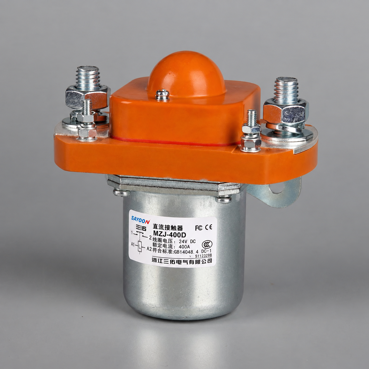
High-side and low-side decisions at a glance
The useful comparison is not “which side is always better?” but “which failure states and measurements can the system tolerate?” The table is deliberately qualitative: allowable current, voltage, leakage, clamp energy, and timing come from the selected devices and application, not from topology alone.
| Decision item | High-side coil switch | Low-side coil switch | Verification question |
|---|---|---|---|
| Controlled conductor | Positive supply feed | Return path | What stays energized when the switch is off? |
| Typical control interface | Sourcing output or suitable high-side driver | Sinking output or suitable low-side driver | Does the specified output topology match the drawing? |
| Off-state coil node | Positive coil terminal may be disconnected from supply | Positive coil terminal may remain at supply potential | What voltage can a technician or diagnostic input see? |
| Gate or output drive | May require level shifting or a dedicated high-side device | Often easier to reference to the local return | Does the driver stay within all common-mode limits? |
| Ground-fault behavior | A short to return can load the high-side output | A short from the switched node to return can bypass the low-side switch | How is the fault detected and cleared? |
| Turn-off energy | Needs a rated recirculation or clamp path | Needs a rated recirculation or clamp path | Where does coil energy flow after command-off? |
The fault descriptions are possibilities, not universal outcomes. Actual behavior depends on wiring, protection, internal driver architecture, grounding, and the coil’s integrated components. Texas Instruments’ inductive-load application brief explains that high-side and low-side topologies require attention to their different demagnetization paths. Its improved inductive-discharge application brief likewise treats the coil’s stored energy as a driver-design requirement rather than an afterthought.
When a high-side driver is attractive
High-side switching is often natural where an industrial controller already provides a sourcing output and the load is intended to have a fixed return. With command-off, the controlled positive feed is removed from the coil. This can make certain short-to-ground and open-load diagnostics easier for an appropriately designed smart output. It does not guarantee that the coil is de-energized under every fault: a welded relay, shorted transistor, backfeed from another circuit, or miswired auxiliary supply can still defeat the intended state.
A high-side MOSFET is not simply a low-side MOSFET moved to another position. Its gate must be driven relative to its moving source node; an appropriate dedicated controller, charge pump, isolated drive, or different device architecture may be required. Check startup, continuous-on time, supply transients, gate drive, reverse connection, and thermal behavior in the actual chosen driver. A bootstrap arrangement that relies on periodic switching cannot be assumed suitable for a coil that must remain energized continuously. TI’s solenoid high-side sensing note illustrates how switch position and circuit observability are linked.
For a contactor with an internal coil controller, the external high-side switch may be switching an electronic input rather than a bare inductance. That distinction affects inrush, leakage, diagnostic pulses, and suppression. Ask for the input-circuit specification before adding an external diode or assuming a conventional coil waveform. Record the voltage actually seen at the input during the lowest supply condition and during a power-up or restart sequence.
When a low-side driver is attractive
A low-side N-channel switch is often easier to control because its source can be tied to a defined local return. It can also fit a PLC sinking output or a simple controller output stage, provided that stage is rated for the real coil duty. This practical simplicity does not mean the whole installation is simpler: the positive feed remains connected to the coil while the switch is off. A conductor fault that connects the switched side to return can energize the coil independently of the command. The design must consider what that means for the larger machine and how the fault is detected.
Return-path layout matters. If coil current and sensitive measurement or control signals share a high-impedance return, switching can shift their reference and create false readings. Keep the high-current coil loop, protective device, measurement reference, and logic return arranged as the approved design specifies. Evaluate the driver transistor’s drain-source voltage during turn-off and the energy dissipated by its clamp over expected repetitions. Short-circuit protection must be assessed with the actual supply and wiring, not just the transistor’s headline current rating.
The power circuit can still be electrically separate from this return path. Never use the main DC negative bus as a convenient coil return unless the system drawing explicitly provides that connection and the isolation strategy allows it. A return borrowed from the wrong domain may compromise monitoring, insulation, and service safety.
Suppression and release time may decide the topology
When coil current is interrupted, inductive energy must go somewhere. A simple diode across a plain DC coil may limit peak voltage but can keep current circulating longer, delaying armature release. A higher-voltage rated clamp can reduce decay time but places more stress on the driver and can create more electromagnetic noise. The correct compromise is determined by the coil manufacturer, driver ratings, required release time, switching rate, and system protection. The choice should not be made from the topology label alone.
Suppression polarity and location differ between a high-side and a low-side layout. A diode drawn across the coil in one application may be unsuitable for a polarity-sensitive electronic coil, or it may duplicate a built-in suppression component. Keep the clamp physically close to the load where the manufacturer’s guidance calls for it, account for cable inductance, and measure the transient at the driver under worst credible operating conditions. TI notes that clamp voltage influences discharge time: an apparently safer low-voltage clamp can extend decay. Our separate opening and closing time article explains why command timing and actual contact timing should be measured, not equated.
Do not confuse a coil’s opening delay with how fast the contactor interrupts a loaded high-voltage circuit. Main-contact separation, arc control, and load current are separate phenomena. Test release under representative mechanical and electrical conditions and verify the desired safe state. If a protective function depends on a time limit, the complete system needs the applicable safety analysis and validation; changing a clamp after validation can change the result.
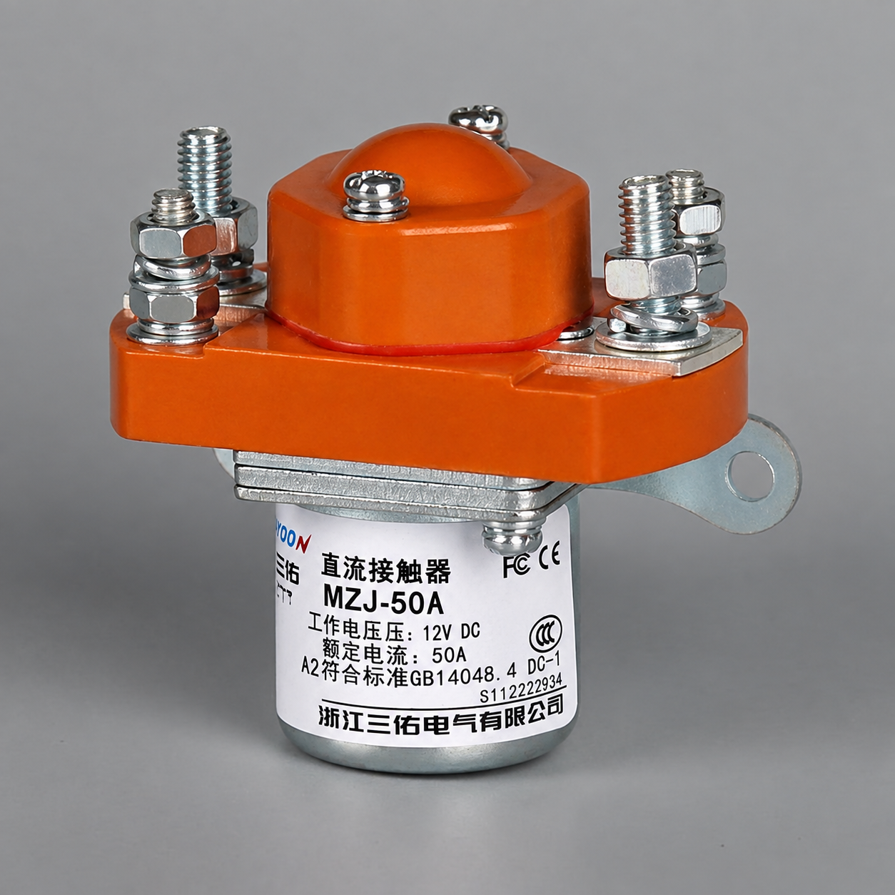
Check diagnostics and fault responses before ordering parts
Define at least five states: command off, command on, wire open, switched-node short to supply, and switched-node short to return. Add driver short-circuit, supply undervoltage, stuck auxiliary feedback, and restart where relevant. For each state, write the expected coil-terminal voltage, expected command-feedback relationship, protective-device action, and system response. This exercise often reveals more than choosing the switch side by habit. Smart outputs may report open-load or short faults, but their diagnostic thresholds and test pulses can interact with electronic coils. Read both manuals.
A coil command is not proof of main-contact position. An auxiliary contact can provide useful feedback, but it may not reveal welded main contacts or stored energy elsewhere. For a high-energy installation, arrange the required independent monitoring and isolation at system level. During maintenance, isolate and verify all hazardous energy using the applicable procedure; a software off command or transistor state is not an isolation device. The U.S. hazardous-energy rule distinguishes control-circuit devices from energy-isolating devices in covered workplaces.
A practical selection and commissioning sequence
- Obtain the exact contactor ordering code, coil input range, pickup and hold requirements, internal suppression details, terminal map, and approved drawing.
- Identify the controller output as sourcing, sinking, relay, or another type; check point rating, group limits, leakage, residual voltage, and inductive-load guidance.
- Choose a topology that makes the desired off-state, grounding, and diagnostic behavior explicit. Document the switch position on the actual schematic.
- Select the driver for current, voltage, transient energy, thermal duty, short-circuit protection, and the required continuous-on behavior.
- Choose only a suppression scheme supported by the exact coil and driver. Confirm polarity and determine whether the device already includes a clamp or economizer.
- Measure coil-terminal voltage and current at pickup, hold, and release. Capture the switch-node transient and feedback transition using suitably rated instruments.
- Test defined fault and restart scenarios under an approved safe procedure; keep the resulting waveforms, settings, and drawing revision with the equipment record.
For product matching, use the Sayoon MZJ-300B product page as a model-specific starting point, not a topology endorsement. The pictured normally closed model also illustrates that contact state and driver side are independent decisions. Begin a broader product comparison with the Hướng dẫn lựa chọn khởi động từ DC (contactor DC), and review công suất tiêu thụ của cuộn dây when sizing the output stage. A useful RFQ states the main-circuit envelope, exact coil supply, control output type, intended driver topology, required release behavior, ambient conditions, switching frequency, and fault-detection requirements.
Video: visualize high-side and low-side switches
This independent electronics explanation shows the basic switch placement and gate-reference difference. It does not prescribe a Sayoon contactor connection or replace a validated wiring diagram.
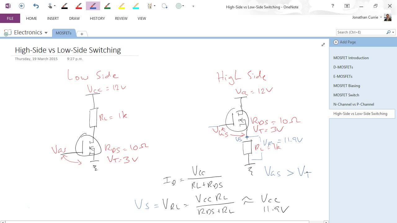
Watch Jonathan Currie’s high-side versus low-side switching explanation.
Các câu hỏi thường gặp
Is a high-side contactor coil driver always safer?
No. It removes the controlled positive feed in normal off-state, but faults, backfeeds, and driver failure can still energize the coil. Compare fault behavior for the complete circuit.
Can a low-side MOSFET drive any DC contactor coil?
No. The MOSFET and gate drive must be rated for pickup, continuous current, turn-off transient, repetition, supply variation, and thermal conditions. Internal coil electronics may add constraints.
Does the main contactor’s normally open or normally closed state determine driver side?
No. Main-contact state and coil-driver placement are separate choices. Use the exact coil electrical specification and system fault requirements to choose the driver.
Can the same flyback diode be copied to either topology?
Do not copy it blindly. The clamp location, polarity, ratings, internal suppression, and release-time requirement must be verified for the chosen coil and switch circuit.





