A railway DC contactor for auxiliary power must match the actual vehicle circuit and its railway service conditions. Begin with the supply voltage envelope, continuous current, converter inrush, current at opening, coil supply, feedback, fault coordination, installation temperature, vibration, and required life. Keep traction switching, auxiliary distribution, and battery backup duties separate. A general-purpose contactor with a similar current rating is not automatically a qualified railway component.
This guide focuses on auxiliary power switching for engineering and purchasing teams. It does not specify a traction contactor, prescribe a train safety function, or claim railway approval for the illustrative products.
Identify the auxiliary circuit before specifying hardware
Locate the switching boundary on the vehicle power diagram. An auxiliary contactor might connect a battery to control loads, isolate a converter input, switch a DC distribution branch, or supervise a backup supply. These circuits can share a nominal voltage while presenting different startup and interruption duties. Label every converter, capacitor bank, parallel source, return conductor, discharge path, and monitoring circuit.
Record what remains energized after the contactor opens. A converter output or backup battery may supply a downstream branch through another path. A command to open one device does not establish the electrical state of the entire vehicle. The boundary drawing should identify the measurements and approved procedures used to verify the intended condition.
Define whether the contactor is used for routine load control, isolation during a service sequence, or a particular abnormal-event response. The applicable vehicle architecture determines its role. Do not assign safety-related functions based on a parts description or an auxiliary contact alone.
Use the railway service conditions as explicit requirements
IEC 60077-1 addresses general service conditions and requirements for electrical equipment on railway rolling stock, including power, auxiliary, control, and indicating circuits. Use the applicable edition, vehicle specifications, and customer requirements to define the qualification package. Reading a standard summary does not establish product compliance.
Translate service conditions into concrete information for the supplier: installation location, temperature range, ventilation, moisture and contamination exposure, altitude, mechanical mounting, shock and vibration conditions, and nearby heat sources. Distinguish the passenger compartment, a protected equipment cabinet, and an exposed underframe installation. Their environments are not interchangeable.
Ask which conditions the proposed ordering code has actually been assessed against and what evidence supports that statement. A claim about an entire product family should not be accepted as evidence for a particular coil, terminal arrangement, auxiliary option, or mounting bracket unless the documents include it.
Separate continuous current from converter startup
Specify the load current over the real operating cycle. Auxiliary equipment may operate intermittently, continue running during station dwell, or start several loads together. Include the thermal effect of repeated starts and the actual conductor and terminal conditions. The rating assessment should represent the installed cabinet rather than an open laboratory bench.
Converter inputs can contain capacitors that draw substantial charging current. Establish whether the system uses controlled charging, a precharge path, or another validated method. Measure the relevant waveform and document the permitted switching sequence. A current limit in software is useful only if its operating conditions, failure response, and interaction with the contactor have been assessed.
Specify opening duty independently. Normal opening after a converter shutdown may differ greatly from opening during a control-power collapse or fault. The supplier needs the DC voltage, current at separation, circuit characteristics, direction, repetition, and protection arrangement for each applicable case.
Build a vehicle-level decision table
| Hộp đựng thiết bị vận hành | Information to establish | Acceptance evidence |
|---|---|---|
| Vehicle startup | Supply minimum, converter charging current, coil pickup | Recorded successful sequence at the supply boundary |
| Normal service | Continuous and cyclic current, cabinet temperature, terminal joints | Installed thermal assessment and applicable device data |
| Supply transfer | Alternative sources, backfeed, dead time, residual voltage | Approved interlocks and state measurements |
| Tắt máy bình thường | Converter current reduction and feedback timing | Sequence verified with production-intent controls |
| Loss of control power | Driver release, remaining load current, protection response | Documented interruption or coordination capability |
| Maintenance access | All energy sources, stored energy, isolation verification | Approved vehicle and workplace procedure |
The table is a review framework. It contains no universal railway voltage, current, timing, or vibration limits. Populate those fields from the vehicle’s applicable specifications and qualification evidence.
Check supply variation and coil control together
A vehicle battery or auxiliary converter does not provide one constant voltage under every condition. Account for charging, discharge, cable drop, startup, and transfer events. Specify main-circuit voltage and coil voltage separately. A contactor ordered for the correct power circuit can still be unusable if its coil option does not match the available control supply.
Check pickup, holding, and release behavior with the actual driver and harness. Repeated coil chatter can damage contacts and undermine state supervision. Investigate the source of a marginal pickup condition rather than repeatedly increasing the command duration. Use the manufacturer’s limits and approved diagnostic procedure.
Suppression circuitry can affect release timing and driver stress. Preserve the exact suppressor option and polarity in purchasing records. Test loss of supply, not only a normal controller command. If a timing requirement depends on an external diode or integrated coil circuit, the replacement review must include that part of the assembly.
Vibration, mounting, and terminal integrity
Mechanical qualification includes the installation. The contactor bracket, fasteners, supporting panel, conductor mass, and harness routing can affect the load transmitted to the device. A product tested with one mounting arrangement is not automatically qualified with a different unsupported busbar or cable bundle.
Maintain the specified orientation and terminal assembly procedure. Route conductors so vehicle movement does not apply avoidable bending loads to the studs or coil connections. Record torque requirements from the actual drawing, including whether they apply to a terminal joint or a mounting fastener. Do not infer a torque value from stud size alone.
Inspect the assembly after the required environmental and mechanical tests. Look for loosened joints, damaged insulation, altered feedback behavior, or changes in switching performance. Visual inspection is one part of acceptance, not a substitute for the required electrical checks.
Coordinate faults and supervise the commanded state
Determine the prospective fault contribution from each source at the switching location. A battery-fed branch and a converter-limited branch can behave differently even when they use the same nominal voltage. Document the protective device, source impedance, cable arrangement, and expected clearing sequence.
Clarify whether the contactor is expected to withstand a fault until protection operates, open under a defined abnormal current, or remain in its current state during a particular event. Obtain evidence for the assigned duty. Do not describe a general contactor as a railway circuit breaker without the relevant product and system documentation.
Supervision should detect disagreement between the command, auxiliary indication, and relevant electrical measurements. Define the response to a failed close, failed open, unexpected residual voltage, or suspected welded contact. A feedback signal can assist a diagnostic strategy, but its relationship to the main contact state must be established.
Acceptance testing and procurement records
Record the vehicle configuration and test revision with every result. If a converter, fuse, cable, control driver, or mounting panel changes after acceptance, assess whether the original evidence remains applicable before approving production.
Build the acceptance matrix around the permitted supply and temperature boundaries, startup, normal stop, transfer, and defined abnormal cases. Use production-intent hardware, wiring, software, protection, and terminal assemblies. Record coil behavior, current, voltage, feedback, and temperature against predetermined criteria.
Keep destructive and hazardous tests within an approved qualified test program. This article is not a live-work instruction. Maintenance arrangements also need the vehicle operator’s rules and the applicable jurisdictional requirements. U.S. hazardous-energy control requirements provide a general workplace reference where applicable; they do not replace railway-specific rules or establish which authority governs a particular operation.
The RFQ should include the boundary diagram, supply envelope, current profiles, make and break cases, coil control, suppression, feedback, installation, protection, and qualification requirements. Preserve the complete ordering code and approved alternatives. Require a documented difference review whenever a replacement changes a material electrical or mechanical characteristic.
Product documents and further learning
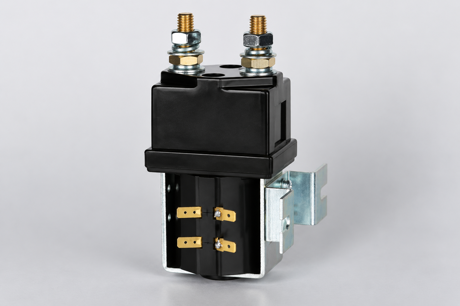
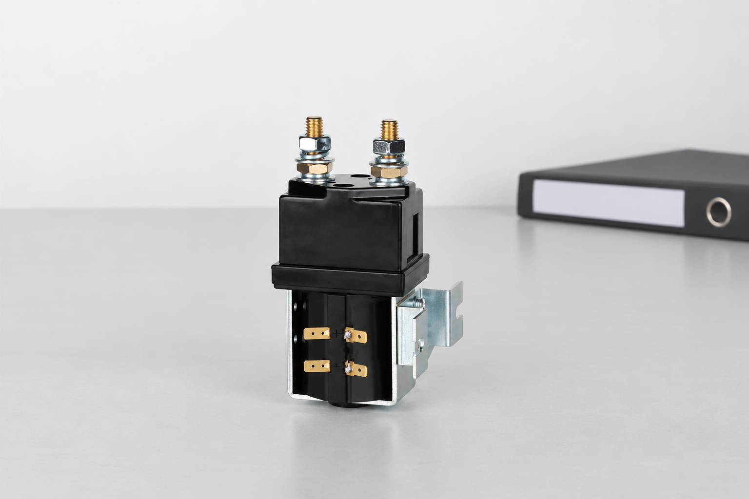
The CZW400A product page illustrates a DC contactor construction for a document request; it is not a statement of railway certification. Review the contactor specification guide, coil supply tolerance guide, và mechanical versus electrical life guide for complementary requirements.
Electrician U’s neutral educational video explains basic contactor operation. Its examples are not a railway wiring procedure or a qualification test.

Preserve the tested configuration as part of the acceptance record. Changes to the device option, driver, protective element, terminal arrangement, mounting, or operating cycle need an assessment of whether the original evidence remains applicable. Keep unresolved differences visible in the approval record rather than treating a matching product name as an automatic release.
Các câu hỏi thường gặp
Is a current rating enough for railway selection?
No. Check switching duty, control supply, feedback, protection, installation, and the applicable railway service and qualification requirements.
Can an auxiliary contactor replace a traction contactor?
Only after the exact duty and qualification requirements are independently assessed; the names do not establish interchangeability.
Does opening one contactor deenergize every circuit?
No. Other sources and stored energy must be considered in the boundary assessment and approved verification procedure.
What is the most useful RFQ attachment?
A boundary diagram accompanied by the operating-state requirement matrix and required qualification evidence.





