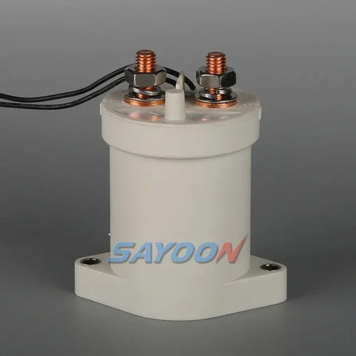
A 20amp contactor is an electrically operated switch with a current rating defined for specified conditions. The 20A label alone does not prove that it can switch every load drawing 20A or less. Confirm the main-circuit AC/DC voltage, load duty, closing and opening events, coil supply, installation and protective coordination. A contactor is not automatically a circuit breaker or maintenance isolator. This guide explains the rating questions to resolve before choosing or replacing a part.
Selection checklist before ordering a 20A contactor
Begin with the circuit drawing and list every source that can energize the load side. A branch can remain energized through a charger, another supply or stored energy even after the main contacts open. State the actual disconnect boundary and retain the independent protection and maintenance-isolation arrangements. Do not infer those functions from a nominal 20A current label.
Next describe the operating load. A motor can have starting or stalled conditions different from its normal running current; a converter input can present capacitor inrush; a heating load can behave differently when cold. Obtain load information and ask for the selected variant’s applicable making and breaking evidence. Do not invent a universal motor-current multiplier or a fixed margin that supposedly covers every case.
Check the control side separately. The coil might use an AC or DC supply and can have internal electronics, suppression or an economizer. Obtain pickup and holding demand, supply tolerance and release behavior from the exact ordering code. A controller output that operates a small relay does not automatically have the capability to drive any contactor coil.
Review conductor and terminal requirements with the actual panel arrangement. Lug fit, conductor support, fastening instructions, clearance and enclosure conditions can affect the installed result. A higher catalog current does not correct a poor joint or prove acceptable operation in a warm enclosure. Use approved manufacturer information and validate the representative assembly rather than choosing solely by apparent size.
For a replacement, compare contact arrangement and normal state as well as the voltage and current fields. A normally closed or latching part can respond differently after control-power loss. Auxiliary contacts carry separate signal duties and do not automatically prove that every main pole has opened. Document how the equipment commands stop, checks feedback and handles recovery before accepting a different construction.
Identify the protective device expected to clear a fault and the event the contactor must withstand or interrupt. A 20A fuse and a 20A contactor are not automatically a coordinated pair. Supply the source and protection information to the design authority or supplier, and retain the supported combination with the final equipment drawing.
Plan acceptance in distinct stages: identity and drawing checks, appropriate functional tests, installed thermal evaluation and evidence for assigned switching events. An audible click or an unloaded continuity reading answers only a small part of those questions. Record the conditions that apply to each result and do not extend a benign sample test to an untested high-energy fault scenario.
Finally, request a traceable ordering code and supporting documents. Keep the coil option, contact diagram, rating conditions, installation instructions and relevant test evidence together. If a repeat order changes a component, construction or control option, review the difference against the original acceptance basis. This is more useful than relying on a generic 20amp description on an online listing.
| Check | Required evidence | Boundary |
|---|---|---|
| Main-circuit duty | AC or DC voltage and load type | A current number is not universal switching approval |
| Coil supply | Supply type, operating range and driver demand | Separate control voltage from the load circuit |
| Closing event | Motor starting or capacitor inrush | Require applicable making-duty evidence |
| Opening event | Current, direction and circuit conditions | Carrying current is not breaking capability |
| Installation | Connections, temperature, enclosure and mounting | Validate the installed configuration |
| Protection | Source fault and coordinated protective device | A contactor alone is not general fault protection |
Use the IEC contactor standard scope and electrical work-practice reference alongside the exact product documents. These references do not certify a proposed installation.
For a documented coil review, compare coil voltage tolerance and coil driver arrangement. For main-contact evidence, use the OEM specification checklist. These links answer complementary questions.
What does the20amp rating actually specify?
A current rating applies with stated voltage, load duty, temperature and installation conditions. Confirm whether the value describes carrying, making or breaking capability. A20A device can have different supported duties for different load types; do not transfer an AC rating to a DC battery branch or treat the number as an unrestricted motor-switching approval.
How Does a 20 Amp Contactor Work?
The functionality of the 20 Amp contactor can be broken down into simple steps:
1. The contactor coil is operated by a low voltage supply (normally between 24V and 120V) and is usually activated from the control circuit through a timer, thermostat or switch.
2. The movement of an electric current passing through the coil produces an electromagnetic field that attracts the movable core or armature within the contactor.
3. Closing Contacts: When the armature moves to contact the two contact points together, it closes the electrical circuit allowing current to flow between the power source and load.
Circuit Breaker—When power is lost to a circuit breaker, its electromagnet is de1_{electrified}, thus releasing its armature and separating the contact points. This action creates an open circuit through which current cannot flow.
The simple and dependable methods of contactors make them the generally preferred solution for these types of applications to switch on and off large electrical systems as electrical safety hazards are minimized, protection against sudden surges, as well as conserving energy when the system is not in use.
Applications of 20 Amp Contactors
20 amp contactors are versatile and can be found in numerous applications, including:
1. HVAC Systems: Contactors are typically used in HVAC (heating, ventilation and air conditioning) installations for controlling a compressor, fan or pump. An example is using a 20 amp contactor in an HVAC circuit that allows a thermostat to turn the equipment either on or off.
2. Appliances & Lights in the Home: Appliances and lights can be controlled automatically through an energy management system. Typically, 20 amp contactors will be used for the automation of such controls, e.g. Water heater Controls and Pool Pumps.
3: Industrial Machine: 20 amp Contactors used to synchronize the operation of motors (electric or hydraulic), conveyor belts, or manufacturing equipment in an industrial facility. The 3-phase power capabilities (example: 20 amp contactor 3 pole) are ideal for these applications.
4. Commercial Structures: These devices are essential for controlling lights, heat, and air conditioning in schools, businesses and chains. They operate reliably and efficiently by operating at high loading power ratings.
Advantages of Using a 20 Amp Contactor
There are several benefits to using a 20 Amp Contactor in your electrical system:
When using a low-voltage control signal, you can operate high power systems from a long distance while maintaining safety.
By effectively controlling current and voltage flow, contactors can reduce the number of electrical hazards (e.g., short circuits and overloads) resulting from electrical faults.
Durable: These contactors have been designed to withstand extremely high currents. They will remain operational under the harshest of conditions.
Energy Efficiency: The energy usage of the equipment can be controlled by using a contactor, allowing you to turn off equipment and lighting that isn’t being used quickly and simply.
Frequently Asked Questions
What is the main purpose of a contactor?
A contactor is used to control electric power’s flow through a circuit. A contactor is in between the electric source and the equipment being used. It enables the operator to manage the operation of high-current machines and equipment from a remote and safe location. It protects against electrical dangers and helps ensure efficient operation.
Can an AC system work without a contactor?
In theory, running an AC unit without a contactor could occur but this is potentially dangerous and not a wise choice. This is because the contactor acts as a safety switch that helps protect your air conditioning unit against overcurrent, which is the amount of electrical power flowing through a circuit at any one time. If the electrically operated contactor is not present, then it is possible for there to be electrical hazards, equipment failure due to damage from excessive current and overloads because of improper installation on an AC unit with no contactors.
What’s the difference between a circuit breaker and a contactor?
While both breakers and contactors work directly with electricity, the purpose/functionality of each is quite different. A circuit breaker is a safety device, designed to detect an over-current situation or short and disconnect electrical current to prevent damage/hazards. A contactor is used for controlling the supply of electrical power to some type of load (i.e. turning something on/off). While the breaker serves mainly as a protective device, the contactor is more a would be referred to as an operational/functional part of an electrical circuit.
What are the three types of contactors?
There are three main types of contactors:
1. Electromagnetic Contactors: This type of contactor is very common; it uses a magnetic coil that opens or closes the supply of electricity. It is highly reliable and is used in residential and industrial applications.
2. Solid State Contactor: Solid state contactors use solid state electronics rather than traditional magnetic types to control the circuit. They offer maximum durability and are the ideal choice in situations where frequent switching operations are necessary.
3. Motor Starters: Motor starters are specifically designed for starting/ stopping motors, most motor starters include an overload protection feature, so they are used with all types of rotating machinery.
Different types of contractors offer various pros and cons based on application, making them adaptable ways to control electrical systems efficiently.