Before releasing a purchase order for a high voltage DC contactor, OEM buyers should verify contact voltage class with headroom, continuous current at a defined duty, rupture data at stated test voltage and time, coil and auxiliary ratings, environmental sealing, and documented electrical life — each as a separate auditable line, not a single ampere label.
This guide is for component engineers and procurement teams who must translate platform requirements into a supplier specification sheet that electrical review can sign. For disconnect-path sizing context on EV programmes, see the HV contactor selection for EV disconnect paths. Browse SEV Series high voltage DC contactors when you are ready to compare published SKUs.

Part 1. Why must OEM teams audit HV DC contactor spec fields before PO release?
A high voltage DC contactor switches or carries DC power paths where contact potential, fault energy, and control feedback must be documented for platform safety files and production audits. Procurement teams searching this term are usually comparing supplier datasheets, not learning what a contactor is.
Two suppliers can both quote “600 A” yet differ in contact voltage ceiling, rupture test voltage, auxiliary contact rating, or coil hold power. Without a field audit, electrical review receives incomplete evidence and PO release stalls while integrators rework the component specification.
| PO audit goal | What a single ampere label hides | Typical reviewer |
|---|---|---|
| Platform voltage fit | Contact voltage class vs nominal pack voltage | System electrical lead |
| Fault energy handling | Rupture current at defined voltage/time | Protection engineer |
| Control integration | Coil inrush, economizer, auxiliary rating | BMS / supervisor designer |
| Export readiness | IP class, stated material compliance scope | Quality / compliance |
The high-voltage system overview at BatteryDesign.net explains that contactor selection spans voltage, continuous current, interrupt capability, and feedback — useful architecture language, not a substitute for your PO line items.
For BESS main-circuit integration steps, cross-read the HVDC contactor integration checklist for BESS when your RFQ covers storage containers rather than traction BDUs.
Part 2. Which voltage and coil fields are often confused on datasheets?
Contact voltage rating describes the potential the open and closed contacts must withstand in service. Coil voltage describes the control circuit that operates the actuator. Mixing the two on an RFQ is one of the most common reasons a valid low-voltage coil option gets paired with an underspecified contact class.
Field separation checklist
- Record maximum sustained DC potential at the contactor terminals in each operating mode.
- Add the headroom your safety process requires above that maximum.
- List coil control voltage separately, including allowable drop during cranking or low-battery events.
- Confirm whether economizer or holding circuits change the steady-state coil demand.
- Attach the schematic node names so supplier and OEM teams reference the same net.
Published SEV400AH parameters list contact voltage (DC V) 5–1000 V and multiple coil voltage options on the product page. Use those fields only when your working voltage and coil supply fit the documented test context.
| Datasheet label | Governs | Common RFQ error |
|---|---|---|
| Contact voltage class | Main path potential | Using nominal pack voltage only |
| Coil rated voltage | Control driver sizing | Assuming 12 V aux equals contact class |
| Pull-in / drop-out band | Driver timing and hold | Omitting temperature corner |
| Clearance / creepage (if published) | Insulation coordination | Not requested on export programmes |
Standards families such as IEC 60947-4-1 discuss contactor utilisation categories at the component level. They inform duty-cycle vocabulary; they do not, by themselves, prove that any one catalog SKU is approved for your platform category.
Part 3. How should buyers read continuous current, duty, and rupture lines?
Continuous current class addresses thermal steady state while the path is closed. Duty cycle or utilisation category captures how often the device switches under load. Rupture or interrupt capability addresses a defined fault-opening event at a stated voltage and time constant — a separate line from everyday driving or charging current.
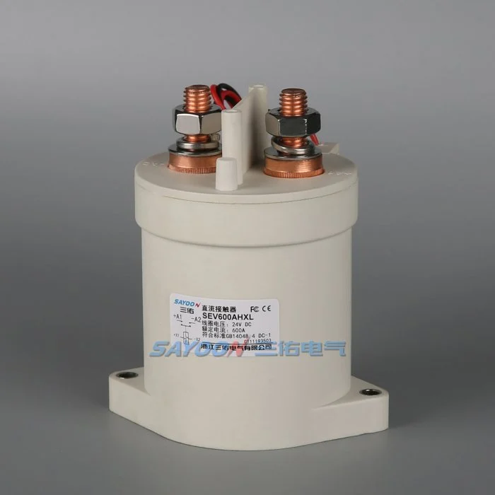
On the published SEV400AH page, load current 400 A DC-1 appears alongside typical fault currents which can be ruptured 1500 A / 5 ms at 48 V DC under the supplier’s stated test conditions. Do not transfer that rupture field to a different voltage or time without written supplier confirmation.
| Rating line | Answers for the OEM file | Does not prove |
|---|---|---|
| Continuous current (e.g., DC-1) | Thermal carry while closed | Every platform fault scenario |
| Electrical life (cycles) | Wear under defined switching | Unlimited fault openings |
| Rupture field | Limited event at stated V/t | Rupture at pack voltage without test data |
| Short-time withstand (if provided) | Overload duration tolerance | Indefinite overload |
Integrators reviewing mobility demand trends can use e-mobility and energy storage demand context for market background, but PO lines must still cite supplier test conditions.
Part 4. What coil, economizer, and auxiliary fields affect BMS integration?
Coil inrush power, economizer hold power, and auxiliary contact ratings determine whether the BMS output stage can command the contactor and whether control logic receives defensible position feedback.
Published SEV400AH coil data includes pull-in at ≯70% and drop-out between ≯35% and ≮5% of rated coil voltage at (20±5) °C, with economizer-style hold power listed as H: Start 30–60 W, Keep 4–10 W under the published table. Map those values to your driver capacity across temperature corners.
Auxiliary contacts are not optional decoration on many programmes. Procurement threads repeatedly ask for auxiliary contact rating relative to sense current because the BMS treats feedback as a safety input. The published SEV400AH optional auxiliary example lists 3 A / 30 VDC on the product page — verify against your sense circuit before reuse.
| Integration field | Supplier should document | Platform owner should document |
|---|---|---|
| Coil peak and hold power | Pull-in / economizer watts | Driver current and thermal limit |
| Auxiliary contact configuration | NO/NC count and rating | Sense current and filtering |
| Command polarity and suppression | Coil polarity notes | Flyback / TVS strategy |
| State feedback timing | Auxiliary actuation delay | BMS debounce and timeout |
Part 5. Which environmental and mechanical fields belong on export RFQs?
Environmental ratings define whether the contactor survives the enclosure, altitude, humidity, and vibration of the deployed product. Mechanical fields — mass, mounting orientation, torque, cable entry — affect BDU layout and service access.
Published SEV400AH data includes IP68 and epoxy sealed construction on the product page. Request the same IP class, temperature range, and sealing technology on the RFQ when your enclosure sees wash-down, marine humidity, or road splash environments.
Export RFQ environmental minimums
- IP class and test method reference
- Operating and storage temperature range
- Shock and vibration class if platform requires it
- Material compliance scope (for example CE, RoHS, FCC where applicable on the cited SKU page)
- Corrosion or coating notes for marine-adjacent programmes
Mechanical mismatch discovered after tooled housings are cut is expensive. Include outline drawing revision, mounting hole pattern, and mass on the same RFQ packet as electrical fields.
Part 6. What RFQ table helps procurement validate a high voltage DC contactor shortlist?
Use one matrix so electrical, procurement, and quality reviewers sign the same record. The table below is a template — replace example values with your platform numbers before PO release.
| RFQ field | Your platform value | Supplier documented value | Pass / review |
|---|---|---|---|
| Maximum working contact voltage | (fill) | (fill) | |
| Continuous current at duty | (fill) | (fill) | |
| Rupture or interrupt at V/t | (fill) | (fill) | |
| Coil voltage and hold power | (fill) | (fill) | |
| Auxiliary contacts | (fill) | (fill) | |
| IP / sealing class | (fill) | (fill) | |
| Electrical life target | (fill) | (fill) | |
| Stated material compliance scope | (fill) | (fill) |
When continuous current sits above the 400 A example class, compare published parameters on the SEV600AH high-voltage DC contactor page and escalate to engineering if your voltage or rupture requirement exceeds cited bounds.
Parallel HEV Series HV DC contactors may fit storage-heavy programmes with different mechanical envelopes — confirm series choice on the RFQ, not from ampere label alone. Review OEM and ODM contactor programmes when coil variants, labeling, or harness integration are in scope.
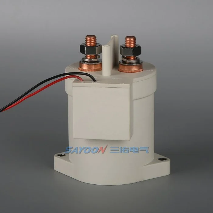
Fit Boundary: Catalog parameters support component-level selection. They do not replace platform safety analysis, protection coordination, or customer-specific homologation evidence.
Part 7. What common datasheet mistakes delay HV DC contactor approvals?
Specification mistakes that recur on OEM programmes
- Rupture line copied without test voltage — reviewers cannot map fault energy to the pack.
- Nominal voltage used instead of maximum — contact class collapses during charge or regeneration peaks.
- Auxiliary contacts assumed without rating — BMS validation fails during end-of-line test.
- Coil hold power omitted — driver overheats after economizer engagement.
- IP class missing on export RFQs — quality audit returns the packet mid-production.
- Single SKU forced across traction and aux paths — see comparison guidance on EV versus standard DC classes in sibling articles before reusing one part number everywhere.
When any line remains blank after supplier response, hold PO release and send datasheet and platform voltage class for engineering confirmation rather than approving a partial table.
References
- BatteryDesign.net — High Voltage System — architecture context for contactor roles
- IEC 60947-4-1 scope — contactor utilisation category framing
- ISO 6469-3 scope (road vehicles — electrical safety) — system-level electrical safety context
FAQ
What specifications matter when selecting a high voltage DC contactor?
Contact voltage class with headroom, continuous current at defined duty, rupture or interrupt data with test voltage and time, coil and auxiliary ratings, environmental IP class, and electrical life under your switching routine. Each field should appear separately on the RFQ and supplier datasheet response.
What is the difference between contact voltage and coil voltage on a DC contactor?
Contact voltage class governs the main power path potential the contacts must withstand. Coil voltage governs the control circuit that operates the actuator. They are specified, tested, and documented independently.
How do OEM teams verify rupture capability on a datasheet?
Require the rupture or interrupt current, test voltage, time constant or duration, and test standard or supplier method reference. Do not extrapolate rupture data from a different voltage without written supplier confirmation.
What auxiliary contact options are required for BMS feedback?
Programmes with safety-related state confirmation need auxiliary contact count, NO/NC configuration, current and voltage rating, and actuation timing relative to main contact movement. Match ratings to the BMS sense circuit, not only to coil control convenience.
Which environmental ratings should appear on an HV DC contactor RFQ?
At minimum: IP class, operating temperature range, sealing technology, and any shock or vibration requirement your enclosure imposes. Add material compliance scope when export markets require documented substance restrictions.
When should buyers escalate from catalog data to engineering review?
Escalate when platform maximum voltage, fault current, duty cycle, or environmental class exceeds published table bounds, when redundant poles or special coil timing are required, or when the safety file demands project-specific test evidence not present on the catalog page.
How do SEV and HEV series differ at RFQ stage?
Both are HV DC contactor families on SAYOON’s site with overlapping voltage-class language but different published SKU envelopes. Compare continuous current, mechanical outline, coil options, and stated compliance scope per series page before freezing a single cross-programme part number.





