Specify a 600A DC contactor from its published rows, not its amp label: the CZW600A and SZJ600A both publish 600 A DC-1 at 48 V with contact voltage capped at ≤60 V, so buses above that class must move to differently rated families such as the ≤150 V QZJ600A, and the engineering file must freeze terminal hardware, coil watts, and fault rupture lines from the exact SKU table before PO release.
These notes are for OEM engineers and panel builders who carry 600 A class DC switching through design review. The class sits inside the CZW series DC contactors pillar on this site, and every number below is a published table row you can audit.
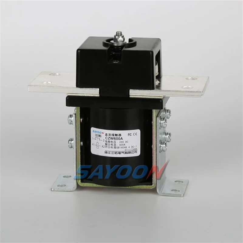
Part 1. Where does a 600A DC contactor fit in heavy industrial DC loads?
A 600A DC contactor shows up where continuous DC current outgrows the 400–500 A classes but does not yet justify kiloamp hardware. Typical homes are electroplating rectifier outputs, heavy DC motor branches, battery test benches, and container-level DC distribution.
The class question is thermal and mechanical at once. Six hundred continuous amps punish every loose joint and undersized busbar, so the device choice and the installation plan must be engineered together rather than sequentially.
| Heavy industrial duty | Why 600 A class appears | First published row to audit |
|---|---|---|
| Electroplating rectifier output | Process current runs continuously | 600 A DC-1 load line |
| Heavy motor branch | Motor plus margin lands over 500 A | Duty profile vs continuous line |
| DC distribution board | Feeder aggregation | Terminal hardware row |
| Battery test / formation | Long charge-discharge blocks | Coil watts and ambient rows |
Neighboring classes are already covered on this site — see the 500A DC contactor engineering notes and the 1000 amp DC contactor considerations when the load sits at those edges.
Part 2. Which published voltage and current lines bound the 600 A class?
The amp number never travels alone. Both LV 600 A SKUs cap contact voltage at ≤60 V, which is the single most-missed line in this class.
| Published field | CZW600A | SZJ600A | QZJ600A |
|---|---|---|---|
| Contact voltage (DC) | ≤60 V | ≤60 V | ≤150 V |
| Load current (DC-1 at 48 V) | 600 A | 600 A | 600 A |
| Coil power line | 20–45 W | Start: 120–170, Keep: 6–13 | Start: 35–65, Keep: 4–10 |
| Load terminal | 2-M8 screws | M12 screw | M12 screw |
| Fault rupture line | 1800 A / 5 ms at 48 V DC | 2000 A / 5 ms at 48 V DC | 2000 A / 5 ms at 48 V DC |
Reading rule one: a 72 V or 80 V bus disqualifies the ≤60 V SKUs regardless of how comfortable the amp line looks — the ≤150 V QZJ600A class is the published escalation path. Reading rule two: the DC-1 line is a 48 V circuit figure, so document your own bus and duty context on the RFQ.
Part 3. How should engineers plan terminals and busbar hardware at 600 A?
Terminal hardware is a published field, not a shop-floor improvisation. The CZW600A page lists 2-M8 load terminals with tightening torque ≤9.0 N.m appropriate, while SZJ600A lists a single M12 stud at ≤30.0 N.m appropriate — two different busbar drilling and torque-tool plans.
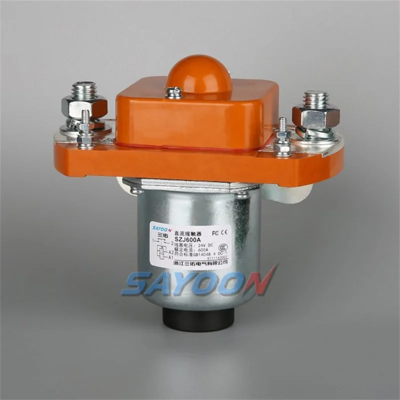
Hardware planning checklist
- Match busbar drilling to the published terminal pattern before purchasing copper.
- Put the published torque values on the work instruction, with the coil-lead torque listed separately.
- Size busbar cross-section and contact area for continuous 600 A, then re-check panel airflow.
- Log ambient at the mounting point against the published -25 to +70 C band.
- Confirm mounting bracket code (2L two vertical default on CZW600A) matches the panel layout.
Forum threads about terminal overheating at this class almost always trace to skipped torque audits or busbar contact area — mechanical discipline, not device defects.
Part 4. What coil power planning does the 600 A class demand?
Coil architecture differs sharply between the two ≤60 V SKUs. CZW600A publishes a flat 20–45 W coil band, while SZJ600A publishes a two-stage line — Start: 120–170 W, Keep: 6–13 W — meaning a strong pull-in stage followed by economized holding.
Panel consequences follow directly. A flat-band coil sizes the control supply once; a Start/Keep coil needs the supply to survive the start surge while the steady-state budget enjoys the low keep watts, and multi-contactor panels must stagger close commands accordingly.
| Coil planning question | CZW600A answer | SZJ600A answer |
|---|---|---|
| Control supply sizing | 20–45 W continuous band | Survive 120–170 W start surge |
| Steady-state budget | Same band while closed | 6–13 W keep line |
| Multi-device close strategy | Parallel close acceptable within supply | Stagger closes to avoid stacked surges |
| Coil voltage options | Published list 6–220 V etc. | Published list 6–150 V etc. |
Part 5. Which fault and life rows belong in the engineering file?
Fault coordination at 600 A starts from the published rupture lines: 1800 A / 5 ms at 48 V DC for CZW600A and 2000 A / 5 ms for SZJ600A. Those are survivable-event windows for coordination studies, not protection ratings, so breakers and fuses still own fault clearing.
Life rows complete the file. Both SKUs publish 10,000 electrical and 300,000 mechanical operations (SZJ600A lists 20,000 electrical), so high-cycle duties need a cycle-count estimate against those lines during design review, not after failures.
| Engineering file row | Why it must be frozen | Source line |
|---|---|---|
| Fault rupture window | Coordination with upstream protection | 1800–2000 A / 5 ms rows |
| Electrical life | Cycle budget vs process duty | 10,000–20,000 operations rows |
| Mechanical life | Long-horizon maintenance planning | 300,000 operations rows |
| Insulation / strength | Dielectric review context | Published insulation rows |
Part 6. Which SAYOON models anchor a 600 A RFQ?
Product recommendation: anchor heavy industrial 600 A RFQs on the CZW600A normally open DC contactor when the bus fits the published ≤60 V class — its 2-M8 hardware, 20–45 W coil band, and 1800 A / 5 ms rupture row give design review a complete published picture.
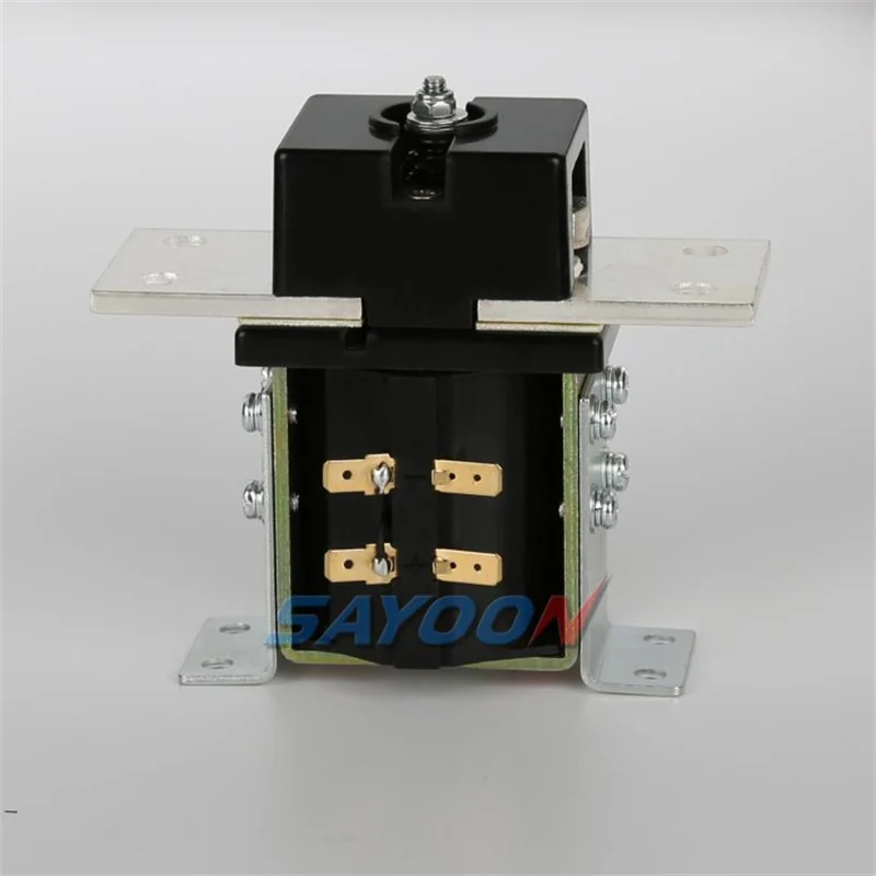
Why not other lines without review: the SZJ600A normally open DC contactor fits panels standardized on M12 hardware that value its 6–13 W keep economy; QZJ600A is the published pointer when the bus exceeds 60 V but stays within its ≤150 V class; loads beyond 600 A continuous belong in the 800 A and 1000 A classes.
Fit Boundary: none of these SKUs is a protection device, none is valid above its published contact voltage class, and duty profiles that exceed published operating or life rows need an engineering review before PO. For methodical field-by-field integration steps, reuse the 400A DC contactor integration checklist pattern one class down.
To move to quotation, send your 600 A duty profile with bus voltage, duty blocks, terminal plan, and coil budget.
Part 7. What engineering mistakes surface at the 600 A class?
- Reading the 600 A label and missing the ≤60 V contact voltage cap.
- Drilling busbar for one M12 stud when the chosen SKU publishes 2-M8 terminals.
- Sizing the control supply for keep watts and browning out on the 120–170 W start surge.
- Treating rupture lines as protection ratings instead of coordination windows.
- Skipping cycle-count estimates against published electrical life on high-cycle processes.
- Ignoring ambient rows inside hot rectifier rooms.
- Releasing the PO without torque values on the installation work instruction.
References
FAQs
What is a 600A DC contactor used for?
Typical duties are electroplating rectifier outputs, heavy DC motor branches, battery test benches, and DC distribution feeders where continuous current lands around the 600 A class.
What voltage can a 600A DC contactor switch?
Read the SKU line, not the amp label: CZW600A and SZJ600A publish contact voltage ≤60 V, while QZJ600A publishes ≤150 V. Buses above the published class disqualify the SKU.
Why does CZW600A use two M8 terminals?
Its published load terminal row lists 2-M8 screws, which spreads the 600 A joint across two studs. The busbar drilling and torque plan must follow that published pattern.
What coil power should panels budget for 600 A class parts?
CZW600A publishes a 20–45 W band, while SZJ600A publishes Start: 120–170 W with Keep: 6–13 W. The control supply must survive start surges and the steady-state budget uses the keep line.
What fault current lines do 600 A SKUs publish?
CZW600A lists 1800 A / 5 ms at 48 V DC and SZJ600A lists 2000 A / 5 ms. Use them in coordination studies; fault clearing itself belongs to breakers and fuses.
Can a 600A DC contactor run a 72 V bus?
Not the ≤60 V SKUs. A 72 V bus points to the QZJ600A published ≤150 V class or a series review with engineering before any PO.
Where should a 600 A RFQ start on this site?
Start at the CZW series pillar, shortlist by published voltage class and terminal hardware, then send the duty profile through the contact page for confirmation.





