The difference between ac and dc contactor coil designs is not a cosmetic nameplate choice. An AC coil builds magnetic force from a pulsating field and inductive reactance, while a DC coil holds with a steady field limited mainly by winding resistance. This article contrasts inrush versus holding behavior, shading rings and core construction, economizers, suppression, and the mismatch failures that show up when the control supply type is wrong.
How AC and DC Contactor Coils Create Magnetic Force
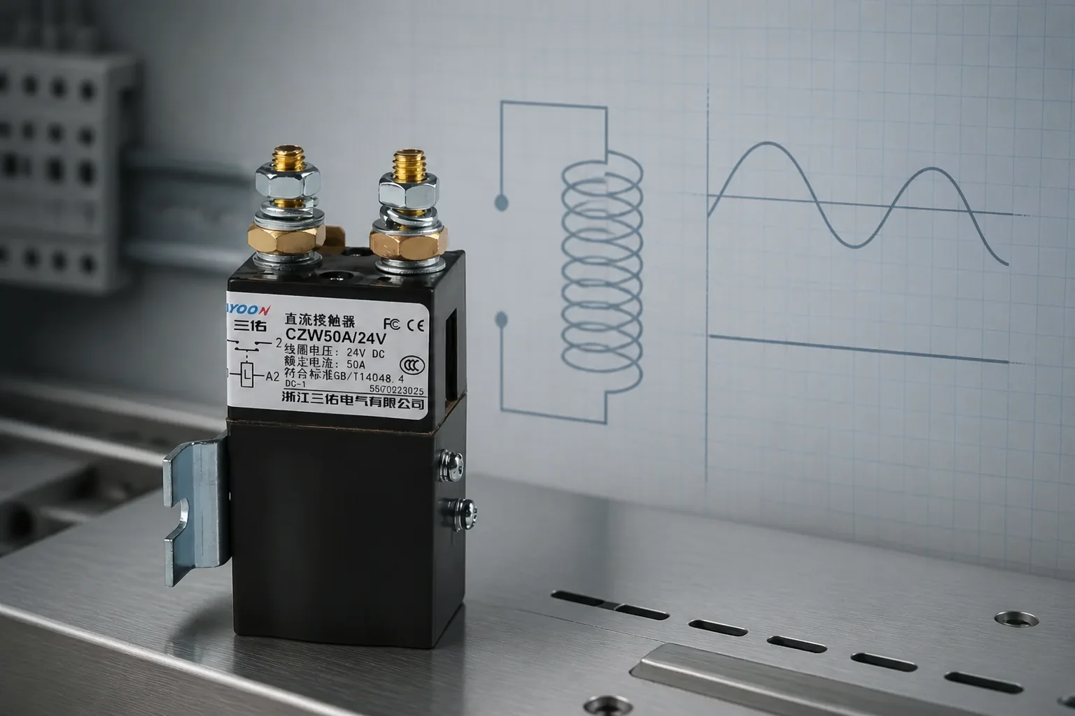
Both coil types do the same job: energize an electromagnet, pull an armature, and close power contacts. The difference is the shape of the magnetic field that does that work.
An AC coil sees a sinusoidal control voltage. Magnetic flux rises and collapses with the waveform, including brief zeros at each half-cycle. A DC coil sees a constant polarity supply, so the field stays essentially steady once current is established.
That single contrast—the practical AC contactor coil vs DC coil split—drives almost every later detail: shading hardware, inrush behavior, audible noise, and which suppressor you may install. If your logic rail is already 24 VDC from a PLC power supply, the coil should be designed for that DC world rather than “close enough” AC hardware of the same voltage number.
Why AC Coils Surge at Pull-In While DC Coils Hold Steady
AC coils self-regulate with armature position. With the magnet open, the air gap is large, impedance is low, and pull-in inrush current is high—commonly on the order of about six to ten times the sealed holding value in industrial coil practice. After the armature seats, inductance rises and current falls to a lower hold level.
DC coils do not get that automatic impedance rise from alternating flux. Steady current is set mainly by winding resistance, so there is no AC-style inrush surge of the same kind. Larger DC magnets often add an economizer or a pull-in/hold drive so continuous heat stays manageable.
| Behavior | Typical AC coil | Typical DC coil |
|---|---|---|
| Magnetic field | Pulsating with the AC waveform | Steady under DC |
| Current limit while held | Resistance plus inductive reactance | Mainly winding resistance (or economizer) |
| Pull-in vs hold | High inrush, then lower sealed current (~6–10× typical) | No AC-style inrush surge; hold near steady current |
| Common control fit | AC control transformers, AC pushbuttons | PLC DC outputs, battery or DC bus panels |
Size the control transformer or DC supply for the real pull-in demand, not only the sealed wattage printed in a catalog line. A transformer that looks fine at holding VA can sag during AC inrush and leave the armature buzzing on the edge of dropout.
Shading Rings, Laminated Cores, and Why AC Coils Buzz
AC magnets need a contactor coil shading ring—also called a shading coil—on the pole face. It is a shorted copper or aluminum turn that induces a flux component roughly ninety degrees out of phase with the main coil. That lagging flux keeps pull force on the armature while the primary flux crosses zero, which reduces chatter and mechanical hammering.
Without a healthy shading ring, the contactor armature tends to relax at each zero crossing. Field reports of line-frequency rattle often point to a broken or loose shading ring, dirty pole faces, or undervoltage that prevents a solid seal.
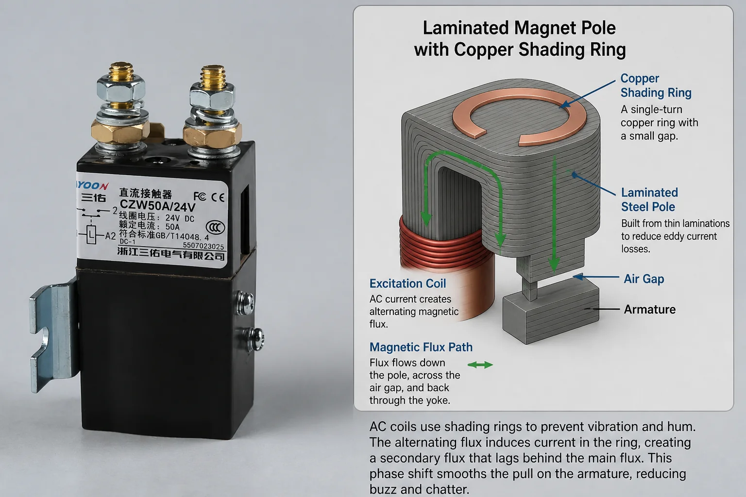
Core construction follows the same physics. AC cores are typically laminated silicon steel so alternating flux does not overheat the iron with eddy currents. Many DC magnetic circuits use a solid core because the flux is steady and eddy heating is far lower.
From the field: When an AC contactor rattles at line frequency after reassembly, technicians often find the shading ring missing, cracked, or loose—or pole faces that never fully seat. Treat loud hum as a magnetic-circuit clue, not only a “noisy coil” annoyance. Source: https://www.eevblog.com/forum/repair/contactor-rattle/
Economizers and Holding Power on DC Contactor Coils
A DC coil must produce enough ampere-turns to slam the armature closed, then keep enough force to hold against the return springs. Because current does not automatically taper the way an AC sealed coil does, continuous heat can climb on larger frames.
A DC coil economizer—or a two-stage pull-in/hold scheme—addresses that. The coil (or its driver) allows a strong pull-in interval, then drops to a lower holding power. Panel rebuilds that try to feed old AC coils from a new 24 VDC rail without that staged behavior are a recurring retrofit mistake.
For OEM designs already on a DC bus, specifying a native DC coil avoids improvising series resistors or homemade capacitor tricks that forums sometimes propose as workarounds. Those hacks may keep a coil from smoking for a while, but they are not a substitute for a coil and magnet system rated for DC.

Coil Suppression: Diodes for DC, RC Paths for AC
Turning a coil off dumps stored magnetic energy into the control circuit. On DC coils, a flyback / freewheeling diode is a common clamp. Some DC contactor model codes even list an optional suppressor diode as a factory function option.
AC coils are different. A diode across an AC coil blocks half of the AC wave and can stop proper operation. AC coils typically need an RC snubber or an MOV-style transient path instead of a simple flyback diode.
| Need | Prefer for AC coils | Prefer for DC coils |
|---|---|---|
| Turn-off spike control | RC snubber or MOV across the coil circuit | Flyback / suppressor diode (or diode+Zener where fast dropout is required) |
| Wrong suppressor risk | Diode half-waves the AC supply | RC may still be used, but diode polarity and rating must match DC |
| Driver notes | Watch AC inrush on small contacts | Match diode and coil current; mind dropout delay with a plain diode |
Match the suppressor to the coil supply type before blaming the PLC for resets or contact welding. Coil EMI and wrong snubbers are frequent enough that industrial notes treat snubber selection as part of coil selection, not an afterthought.
What Happens When Coil Supply Type Is Wrong
Nominal voltage equality does not authorize a swap. A 24 V AC coil on 24 V DC loses the inductive reactance that normally limits AC current, so current rises toward V/R and the winding can overheat within seconds to minutes. Forum reports describe rapid burnout and, in severe cases, welded main contacts after the miswire.
The reverse mistake—feeding an AC waveform into a DC-only magnet without the intended rectifier/filter path—creates its own chatter and heating problems. Direct substitution of AC coils onto a DC PLC rail is the failure mode OEM redesigns should design out, not troubleshoot later.
Important: If you are converting a panel from AC control power to DC logic, plan for DC-rated coils (or a retained AC control transformer for legacy AC coils). Do not treat matching nameplate volts as a universal coil language. Source: industrial forum reports on AC-coil DC misapplication.
Selecting a DC Coil Contactor for OEM Control Designs
When the control supply is DC and the main path must switch DC loads, start from a DC contactor family whose coil options are listed as DC voltages—not from an AC motor contactor that happens to share a similar ampere headline.
The CZW series DC contactor hub is the family entry for SAYOON’s CZW line. For a concrete normally open example, the CZW50A normally open DC contactor lists a 1 NO contact form and coil rated voltages as DC values such as 12 V, 24 V, 36 V, 48 V, and other DC options on the live product table. Coil power is listed in the 5–10 W range for that model, and the model implication table includes an optional suppressor-diode function code.
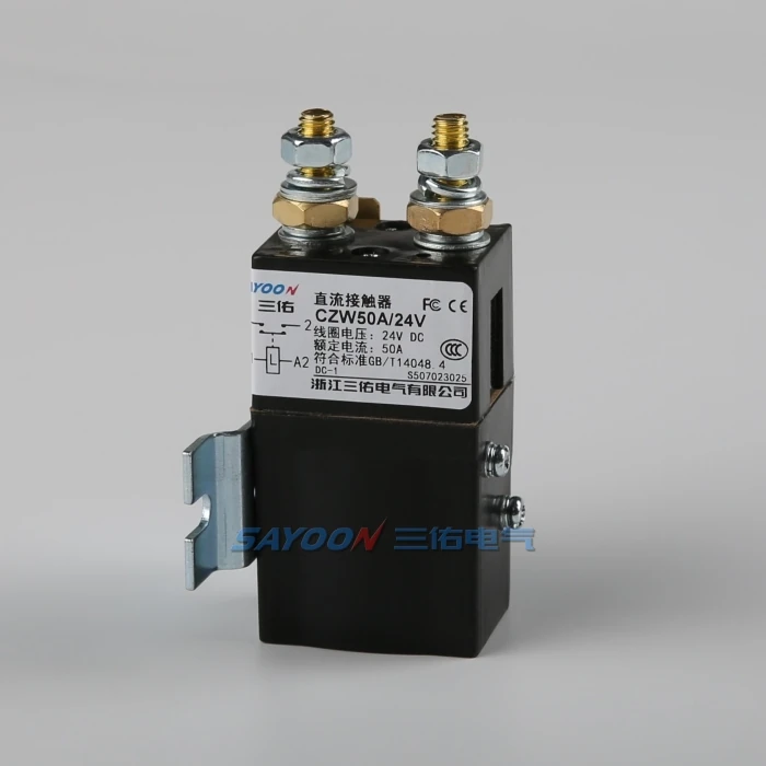
Use CZW50A when your drawing needs a normally open DC main path and a DC coil voltage that matches the control rail. Choose another contact form or series when the schematic needs normally closed, reversing, or a different current class—still confirming the selected datasheet rather than assuming family-wide ratings.
FAQ
What is the difference between an AC contactor coil and a DC contactor coil?
An AC coil works with a pulsating field, inductive reactance, and usually a shading ring. A DC coil works with a steady field limited mainly by resistance, often with an economizer on larger sizes, and without a shading ring in normal DC magnets.
Why do AC contactor coils buzz or hum?
AC flux crosses zero each half-cycle. A healthy shading ring and a fully seated armature keep the magnet quiet enough for service; undervoltage, contamination, or a damaged shading ring can create line-frequency buzz or rattle.
Can I power an AC coil from DC at the same nominal voltage?
No. Without AC reactance, coil current rises toward the DC resistance limit and the winding can burn quickly. Replace with a DC-rated coil or keep a true AC control supply.
Do DC coils need an economizer?
Not every small DC coil does, but larger DC magnets commonly use an economizer or pull-in/hold staging because they lack the AC coil’s automatic current taper after sealing.
Can I put a flyback diode across an AC coil?
No. A diode blocks half of the AC waveform and can prevent the coil from operating. Use RC or MOV-style suppression on AC coils; reserve simple flyback diodes for DC coils.
Are DC coils better for PLC outputs?
Often yes, when the PLC and control PSU are already DC, because inrush and magnetic behavior align better with DC outputs. Still confirm coil current, suppression, and the output module rating.
What DC coil voltages does CZW50A list?
The live CZW50A table lists coil rated voltage as DC options including 6 V, 12 V, 24 V, 36 V, 48 V, 60 V, 72 V, 84 V, 120 V, 150 V, and similar DC values. Match the ordered coil voltage to the control rail on the drawing.
What should I check before replacing a contactor coil?
Confirm AC versus DC type, rated voltage, inrush/holding burden, duty cycle, ambient temperature, and the suppressor that belongs with that coil. Physical fit alone is not enough.





