Quick answer: A battery string contactor connects one battery string to a shared BESS DC bus only after the controller proves compatible voltage, polarity, insulation, precharge, and communications. In parallel racks, it also isolates a faulty or serviced string without allowing the remaining strings to back-feed it. Safe operation depends on coordinated sequencing, current-sharing limits, string fuses, voltage sensing, feedback diagnostics, and controlled discharge.
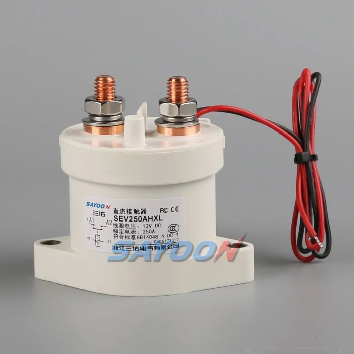
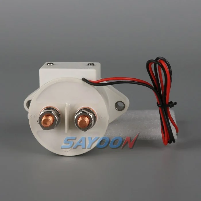
This guide turns the topic into a reviewable BESS design, commissioning, and sourcing workflow. It uses a real Sayoon contactor as the visual product reference while keeping every rating, sequence, and safety decision tied to the final system and current manufacturer documentation.
Engineering decision map
| System state | Expected electrical condition | Design focus |
|---|---|---|
| String offline | Both mains open; bus may remain live | Prove isolation on both sides |
| Precharge | Precharge path active; mains open | Limit equalization current and verify voltage |
| Parallel online | Mains closed after voltage match | Monitor string current and sharing |
| String fault | Affected string opens; others remain controlled | Coordinate contactor, fuse, PCS, and discharge |
Product reference and scope
The SEV250AHXL sealed high-voltage DC contactor is a relevant real product-family example. Review the high-voltage DC contactor guides and DC contactor selection guide for the broader workflow. A visual match or nominal current does not approve a model for a BESS. Confirm voltage, carry current, make and break duty, polarity, insulation, temperature, environment, life, mounting, driver, and protection together.
Why each string needs a controlled boundary
Parallel battery strings share a bus but do not remain identical. State of charge, temperature, internal resistance, cable resistance, and aging change each string voltage and current. A battery string contactor gives the BMS a controlled boundary for startup, fault containment, maintenance, and availability management. It is not a replacement for the string fuse and cannot correct cell imbalance.
The one-line diagram should show positive and negative mains, precharge branch, fuse, service disconnect, voltage and current sensors, insulation monitoring, auxiliary feedback, and the shared PCS connection. Mark every section that can remain energized when a single string is offline.
Match voltage before paralleling
Closing two strings with different open-circuit voltages can create a large equalization current limited mainly by impedance. Before closure, compare string voltage and bus voltage with sensors that have known accuracy and timing. Confirm polarity and communications. Use precharge or another approved matching method where required.
The acceptance window must include sensor error, contactor timing, capacitance, cable impedance, and the BMS strategy. A fixed delay does not prove voltage match. If the bus is outside the approved window, stop the sequence, identify the energizing source, and prevent repeated closure attempts.
Sequence the contactors and precharge path
A typical sequence verifies interlocks and insulation, closes the designated return path, activates precharge, watches bus voltage rise, closes the main path, then opens or de-energizes the precharge branch as designed. The exact order depends on the system. Document the expected voltage and feedback after every step.
On shutdown, reduce PCS current when possible, open the required mains, confirm current stops, and verify the isolated side. The shared bus can stay energized from other strings, so pack-side and bus-side measurements are both necessary.
Manage current sharing after closure
Once parallel, current does not divide perfectly. A lower-resistance or higher-voltage string can take more charge or discharge current. Monitor each string rather than relying only on total PCS current. Set warning and trip logic from validated battery and conductor limits, including sensor uncertainty and transient sharing.
Investigate persistent imbalance through state of charge, cell temperature, contact resistance, fuse and busbar joints, cable length, sensor calibration, and BMS estimates. Do not repeatedly open and close a string to force sharing unless the approved control strategy specifically supports that behavior.
Isolate faults without creating another fault
A string overcurrent, insulation fault, thermal event, communications loss, or contactor mismatch may require isolation. The controller must decide whether to reduce PCS power first, open the affected string, or shut the common bus. Opening under current must remain within the contactor duty and protection concept.
Other strings can feed the fault through the bus until the isolation and fuse sequence completes. Calculate prospective current and clearing energy. Preserve first-fault timing so the team can distinguish a battery fault from a welded contactor, failed driver, or incorrect current sensor.
Detect welded and stuck-open conditions
Compare contactor command, coil current, auxiliary feedback, string current, string voltage, and bus voltage. A closed auxiliary contact does not prove low-resistance main conduction. An open auxiliary contact does not prove that bus voltage has disappeared. Evaluate the complete circuit, including a parallel back-feed path.
After an open command, a persistent current is strong evidence of an unintended path. Similar voltage on both sides may be normal when the shared bus remains energized and the isolated string voltage is close, so use an approved diagnostic stimulus or discharge path rather than voltage equality alone.
Commission strings one at a time
Commission with production-intent racks, busbars, controllers, sensors, fuses, and PCS. Verify polarity, part numbers, drawings, terminal torque, coil supply, suppression, auxiliary logic, and sensor calibration before energizing. Bring one string online through the complete sequence while recording synchronized waveforms.
Repeat for each physical position, then test parallel connection, controlled removal of one string, communication loss, low control voltage, sensor faults, failed precharge, emergency stop, and restart restrictions. Use authorized procedures for hazardous energy and do not bypass interlocks to accelerate testing.
Document the operating envelope
Record the number of strings, battery voltage range, permissible voltage mismatch, charge and discharge currents, transient sharing, current at make and break, precharge capacitance and resistance, fault current, fuse clearing, temperature, enclosure, conductor resistance, switching cycles, coil driver, feedback, and service strategy.
The SEV250AHXL shown here is a product-family reference. Confirm the final part number and product-specific data for the real string duty. Keep calculations, raw waveforms, settings, deviations, and approvals with the as-built configuration.
Manage changes and periodic checks
Review the original evidence whenever cell chemistry, string count, PCS firmware, cable length, busbar, fuse, cooling, sensor calibration, contactor coil, driver suppression, or operating schedule changes. A physically interchangeable part can alter current sharing, pickup margin, release time, or fault coordination. Identify the affected assumptions and repeat the necessary tests.
During maintenance, inspect terminal joints, barriers, conductors, heat evidence, contamination, mounting, control wiring, and diagnostic history. Compare voltage drop and temperature only under comparable current and measurement conditions. After replacement work, exercise the complete approved sequence under representative load and confirm that one isolated string cannot be energized through the common bus or an auxiliary path. Record the reviewer and final disposition.
Safety and evidence controls
Treat the battery, common bus, converter capacitors, parallel racks, auxiliary supplies, and test equipment as hazardous energy sources until an authorized person has applied the site isolation procedure and verified the required state with rated instruments. Do not bridge feedback pins, force a coil, defeat HV interlocks, or open a device outside its qualified switching duty. A BESS can remain energized from a direction that is not obvious on a simplified schematic.
Build acceptance limits from the exact product data, approved system requirements, and representative testing. Record the complete ordering code, drawing revision, coil option, terminal map, conductor arrangement, instrument locations, calibration, temperature, software version, raw waveforms, pass/fail criteria, deviations, and reviewers. Separate measured facts from interpretations. When evidence is missing, record an open action instead of inserting a typical value.
Related engineering guides
Use the precharge resistor sizing guide, contactor feedback plausibility guide, short-circuit withstand guide, and insulation coordination guide as complementary checks. These pages cover different decisions and should be applied to the same approved system boundary.
Educational video
What is a Contactor and How Does it Work? by Electrician U provides visual background on contactor operation and high-voltage switching. It does not replace the written design requirements or the product-specific validation.
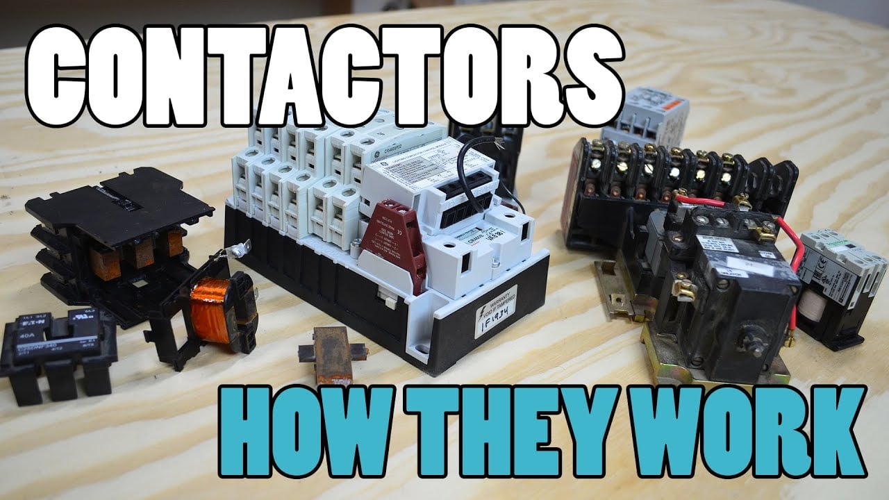
Watch the educational video on YouTube.
Frequently asked questions
What is the first rule for battery string contactor?
Define the circuit boundary and every source that can energize it, then verify the exact device duty against measured voltage and current waveforms.
Can auxiliary feedback prove the main contacts are open?
No. Correlate auxiliary state with bus voltage, string current, coil current, timing, and all possible back-feed paths.
Should a contactor replace a string fuse?
No. A contactor provides controlled switching while a fuse provides fault-current protection. Their withstand and clearing duties must be coordinated.
What data belongs in a BESS contactor RFQ?
Include voltage range, current waveforms, make and break duty, current direction, precharge, fault current, protection, temperature, mounting, coil control, feedback, and life target.
Authoritative references
- OSHA 1910.147 — control of hazardous energy
- OSHA 1910.333 — electrical work practices
- IEC 60947-4-1 — contactors and motor-starters
- U.S. Department of Energy — energy storage
Use the editions and requirements adopted by the project. Standards and product data may change, so the responsible engineering team must confirm the final design.





