A 40A DC contactor should be chosen from the actual load voltage, installed current profile and required switching events. The 40A label alone does not prove suitability for a motor, capacitor bank or hot enclosure. Confirm the coil variant, main-contact DC carrying and interruption evidence, conductor requirements and control-power-loss behavior separately. This guide focuses on a compact DC branch or auxiliary panel drawing around a 40A requirement. Any numerical example below is an illustrative engineering exercise, not a published rating for the pictured product.
Describe the forty-amp requirement before selecting a part
First state what forty amperes represents: continuous operating current, a short peak, a protection setting or a desired catalog class. These are different inputs. A branch that runs steadily near 40A needs an installed thermal assessment; a load that reaches 40A only briefly still needs supported closing and opening behavior.
Record the load type and voltage range together. Resistive heaters, motors and electronic converters can present different duty at the same current. A contactor selected for a lightly inductive branch cannot be assumed suitable for every forty-amp motor event.
Write a short duty description with current, duration, repetition and permitted switching states. Attach it to the schematic so purchasing can compare the same requirement across quotations. Avoid rounding an incomplete load description into a model number.
Distinguish a load disconnect from a protective device
A remote contactor usually performs a commanded switching function. It does not automatically provide overcurrent protection, fault interruption or approved maintenance isolation. Show the fuse or breaker and the required service-disconnect arrangement on the branch drawing.
If a forty-amp fuse protects the circuit, that does not make every 40A contactor a coordinated combination. Protection behavior depends on the source, prospective fault and protective-device characteristics. Obtain the relevant evidence and define what the contactor must withstand or interrupt.
Also consider another source feeding the disconnected side. Chargers, parallel branches and stored energy can leave the load energized after opening. A controller’s off command is not the same as a verified safe-work condition. Keep those functions and procedures distinct in the panel documentation.
Use a resistance example to understand local heating
For a simple steady-current illustration, local resistive loss is P = I²R. If an arbitrary connection resistance is 0.5 milliohm,40A produces 40² ×0.0005 =0.8W at that connection. This hypothetical number does not state the resistance or permissible temperature of a Sayoon product.
The example shows why apparently small resistance matters. Actual installed heating also depends on thermal paths, ambient conditions, duty profile, conductor size and neighboring heat sources. A single calculated loss does not predict the maximum terminal temperature.
Use qualified measurements and the manufacturer’s criteria to investigate a warm joint. Do not accept a high-resistance assembly by adding cooling without resolving the cause. Equally, do not condemn a contactor from an isolated temperature reading without knowing its current, ambient conditions and approved installation.
Select terminals and conductors as an assembly
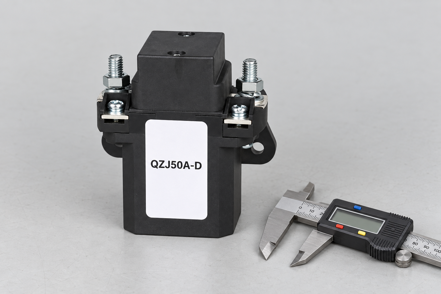
Check conductor material, cross-section, lug construction, terminal dimensions and the manufacturer’s connection instructions. A lug that physically fits can still impose the wrong mechanical load or leave inadequate clearance. The contactor’s installed duty should be assessed with the actual connections.
Specify fastening requirements from approved documentation. Do not invent a torque value from the stud diameter or reuse a value belonging to another model. Include conductor support and bending space so vibration or maintenance does not load the contactor terminals unexpectedly.
For a compact branch panel, verify space around both the main and coil connections. Accessibility, protective covers and separation from adjacent circuits deserve attention even when the main current appears moderate. The panel enclosure and workmanship can determine whether an otherwise suitable contactor remains acceptable in service.
Check closing duty for the actual branch load
A forty-amp running current does not describe the moment of closure. A motor can draw a different starting current; an electronic load can present input-capacitor inrush. Identify the circuit state before the contactor closes and whether a controller or precharge path changes that event.
For resistive heating, review cold-versus-hot behavior and the repetition of switching. Do not assume every heating element behaves like an ideal constant resistor. Obtain the load supplier’s information when the starting condition is not known.
A higher carrying-current class may offer a useful option, but it is not proof of supported making duty. Send the supplier the expected closing conditions and request applicable evidence. Where no such information exists, leave the selection unresolved rather than claiming a fixed percentage margin makes it safe.
Specify coil current and the control interface separately
The contactor’s main-current class does not identify its coil demand. Obtain pickup, hold and release information for the exact coil option. Compare the required control load with the output stage, power supply and wiring path at the contactor terminals.
Check whether internal suppression or electronics impose polarity. Adding an external suppression device without identifying the internal circuit can change release behavior or introduce an unwanted interaction. Keep the selected suppression arrangement on the control schematic.
Describe the required state after loss of coil power. For a conventional non-latching normally open construction, the intact mechanism is expected to open when de-energized, but failures must still be assessed. Do not substitute a normally closed or latching variant solely because its current and mounting dimensions look convenient.
Plan repeated switching and service life
Mechanical life and electrical life answer different questions. A mechanism can operate without load many times yet experience a different life when repeatedly making or breaking a real DC branch. Define frequency, switched current, load conditions and expected service duration.
If the controller can cycle the contactor rapidly, review whether that operating mode belongs to the selected construction’s documented duty. Avoid treating software control as unlimited switching capability. Chatter or repeated supply dips can create unwanted operations that deserve correction at the control circuit.
For maintainable equipment, define inspection triggers and replacement evidence. Trends in heating, voltage drop or functional response should be evaluated against controlled conditions. A generic replacement interval copied from a different application is not an adequate service-life assessment for the actual branch.
Verify a sample before releasing the purchase
Start with identity, drawing revision and coil option. Check the contact arrangement, mounting and connection requirements before functional testing. An incoming specimen should match the supported variant, including accessories and auxiliary contacts that the equipment actually uses.
Validate representative installed carrying duty and the assigned switching sequence in a suitable setup. Record current, temperature conditions, supply voltage and feedback response, rather than relying on an audible click. The sample test should answer the application’s defined questions without attempting an uncontrolled high-energy fault demonstration.
Before accepting the quotation, retain the full duty packet and supplier response. For a replacement, compare all changed fields with the original approved configuration. A larger nominal-current model is still a design change when it alters the coil circuit, terminal arrangement or main-contact operating state.
Selection evidence checklist
| Review field | Information to provide | Acceptance boundary |
|---|---|---|
| Load profile | Meaning of 40A and operating duration | Separate continuous and peak demand |
| Main voltage | Actual DC range and source paths | No transfer of an AC rating |
| Connections | Approved conductor, lug and torque information | Evaluate the complete installed joint |
| Closing event | Motor or capacitor starting conditions | Require making evidence |
| Coil option | Supply range and driver capability | Check voltage at the coil terminals |
| Duty repetition | Expected switching frequency and load | Distinguish mechanical and electrical life |
This qualitative checklist organizes evidence; it does not state product ratings or universal acceptance limits. Numerical examples elsewhere are explicitly hypothetical.
Product information and related review tools
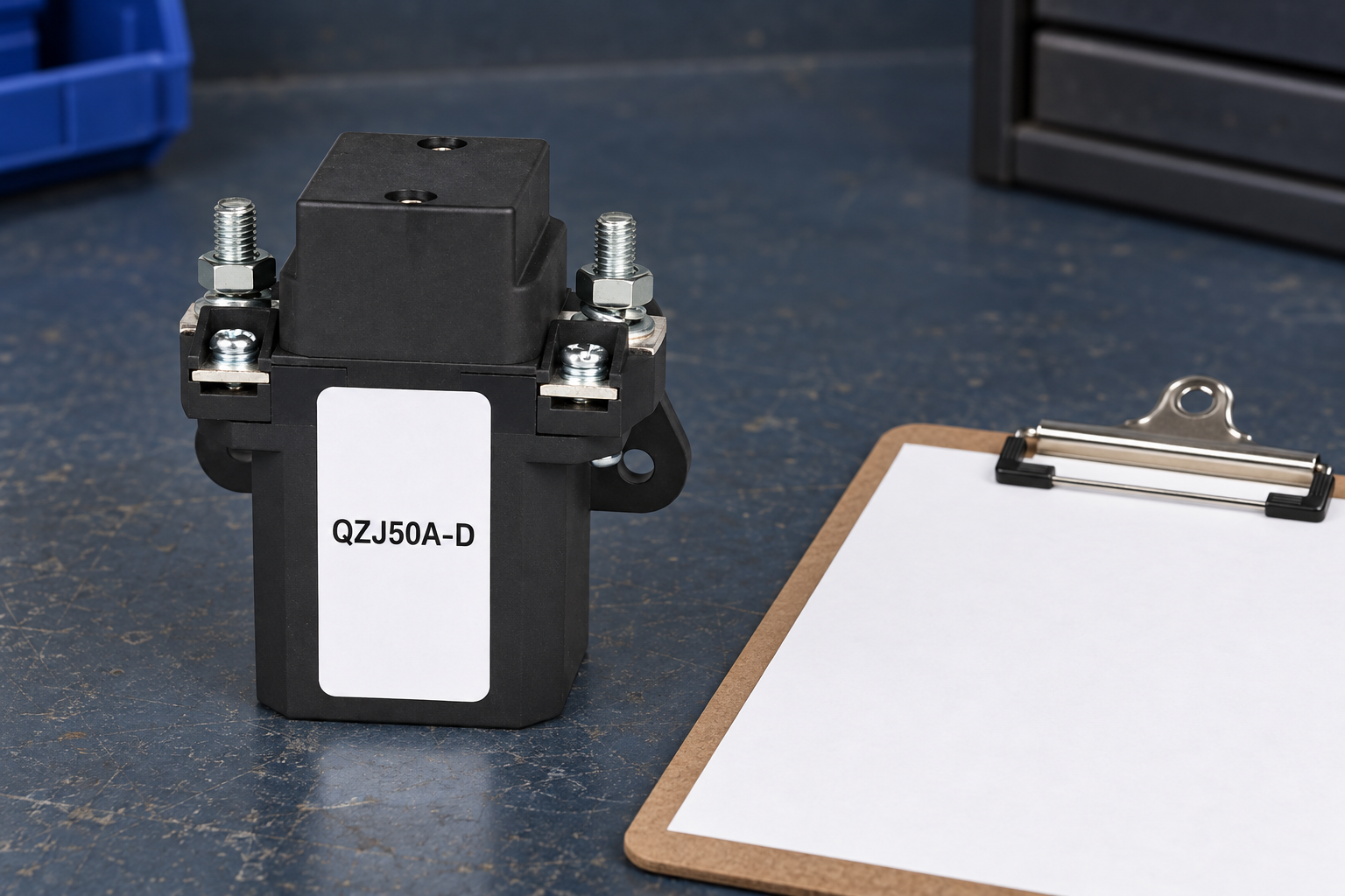
The QZJ50A-D product information is the reference for the external construction shown. The pictured variant may have a different current class or contact arrangement from the requirement. It is not an automatic recommendation or a statement that every discussed duty is supported. Obtain the exact ordering code, drawing and applicable ratings before selection.
Use the OEM specification evidence checklist to separate documented limits from unresolved assumptions. Complement the main-circuit review with coil voltage tolerance and mechanical versus electrical life. Those topics address distinct control and lifecycle questions rather than replacing this article’s assigned selection boundary.
Sources and safe validation
Scope references: IEC60947-4-1 contactor and motor-starter standard overview; U.S. electrical work-practice requirements. Apply relevant equipment requirements and approved manufacturer documentation. These links do not certify the illustrated product for a proposed duty. A commanded contact opening does not replace appropriate isolation and verification before servicing.
Educational contactor mechanism video
Electrician U explains the electromagnetic operating principle. This supports understanding of coil and contact operation, not a particular voltage, current, protection function or pictured variant’s qualification. The article’s selection evidence remains necessary whether or not the video is watched.

Frequently asked questions
Is a 40A contactor suitable for every load below 40A?
No. Voltage, load type, switching duty and installed temperature conditions must also be supported.
Can I use the fuse rating as the contactor selection?
No. The protective device and contactor require appropriate coordination for the source and fault conditions.
Does the 0.8W example describe the product shown?
No. It uses an arbitrary resistance to illustrate I²R heating; it is not product data.
What should a buyer include in a 40A RFQ?
Include voltage range, duty profile, making and breaking conditions, coil requirements, protection and installation information.





