A DC contactor coil power supply must support the combined current waveform of every control load that can operate together, while keeping voltage at each coil inside its documented operating range. Adding hold watts is only the continuous-load check. Also review simultaneous pickup, the duration of each demand, other control equipment, cable loss, temperature derating, and the supply’s overload response. Do not assume every DC coil has a large inrush peak: a plain winding and an electronically economized coil can behave differently. Obtain the exact coil data or measure the intended assembly before approving a supply.
Define the control-power boundary
Start with a control-power drawing rather than the contactor’s headline current rating. The ampere marking for the main contacts does not state the current required by the coil. Identify the supply feeding the coil driver, the controller, sensors, indicator lamps, interface relays, and any other loads sharing that output. A controller supply and a coil supply may be separate, or they may be branches of the same source.
List normal startup, normal running, commanded stop, emergency response, brownout recovery, and maintenance modes. Record which devices can be energized in each state. A sequence that usually closes one contactor at a time may close several after a restart or during a manual service command. Only count diversity when the control design enforces it under the conditions being reviewed. Write down that assumption so a future software change does not silently invalidate the budget.
Collect the correct coil demand
For each ordering code, request the permitted terminal-voltage range, pickup behavior, hold current, internal electronics, and any economizer transition. Ask whether the data describe cold or warm operation and which supply voltage was used. When a manufacturer supplies only nominal power, identify what that number represents before converting it to current.
For a simple steady DC load, current can be estimated as power divided by voltage. That arithmetic does not create a dynamic current waveform. An internal controller may draw a different current during startup; an external driver may limit or pulse current; and a cold winding may differ from a warm winding. Keep calculated steady values separate from measured or documented transient values. The existing coil-power guide explains the single-device measurement; this article addresses the shared supply decision.
Build a time-based current budget
Represent the required source current as I_total(t) = I_background(t) + the sum of I_coil,k(t) for all active branches. Here t is time, k identifies a coil branch, and background current includes the remaining controls on the same output. Use amperes consistently and align the traces to the actual command sequence. The highest instantaneous demand and the longest sustained demand may occur in different operating modes.
Then calculate the continuous demand from the allowed running states. Compare that demand with the supply’s available output under the actual input voltage, enclosure temperature, mounting orientation, and installation instructions. A short-term peak capability is not extra continuous capacity. Likewise, a continuous rating alone does not explain what happens during a brief overload. Preserve both checks in the review rather than choosing whichever catalog number looks more favorable.
Worked example with hypothetical values
Consider a hypothetical 24 V control system with three coils and a controller load. These values are teaching assumptions, not JCC200A specifications or a recommended supply size. Suppose each coil requires a documented 1.2 A during a 0.10 second pickup interval and 0.25 A afterward, while the remaining controls draw 0.60 A. If all three pickup intervals overlap, the assumed demand is 0.60 + 3 × 1.2 = 4.20 A. The assumed steady demand is 0.60 + 3 × 0.25 = 1.35 A.
Those figures describe two requirements, not an automatic approval for a 1.35 A or 4.20 A supply. The designer must check the candidate supply’s transient envelope and terminal voltage throughout the 0.10 second event. If an enforced sequence allows only one pickup at a time while two coils already hold, the assumed maximum becomes 0.60 + 1.2 + 2 × 0.25 = 2.30 A. That reduction is valid only for the stated sequence and assumptions. A restart path that bypasses the sequence restores the simultaneous case.
Review overload behavior and recovery
Ask what the supply does when the demand exceeds its available output. Depending on the exact model, it may limit current, reduce output voltage, switch off, or retry. A repeated retry can prevent the coils from completing their intended motion even when average power appears acceptable. Read the actual overload characteristic and recovery conditions; the words industrial power supply do not define this behavior.
MEAN WELL’s published FAQ discusses distinct overload responses, while its product documentation demonstrates that capabilities vary by model. Use those sources to understand the distinction, then obtain the specific supply data for the design. Do not transfer a peak-current allowance from another series or assume that a motor-start recommendation applies unchanged to a contactor coil. Confirm duration, repetition, temperature conditions, and recovery time for the chosen unit.
Check voltage at the farthest coil
A satisfactory voltage at the supply terminals does not prove satisfactory voltage at the coil. Include the positive conductor, return conductor, driver output, connectors, protective devices, and shared connections in the path. Under defined steady conditions, a resistive path drop follows V_drop = I × R. Use the current and resistance relevant to that branch and operating condition; a shared return can carry several branch currents.
Capture coil-terminal voltage during the worst allowed combination of loads. Compare it with the exact documented requirements for pickup and hold, including any timing conditions. Increasing the supply setpoint is not a universal repair: nearby equipment and lightly loaded branches must remain within their own voltage limits. If a harness change is needed, review conductor protection, connector suitability, installation, and thermal behavior together.
Use an evidence table for selection
The following qualitative table separates the questions that a single wattage number cannot answer. It is a planning aid, not a product-rating table. Assign an owner and evidence reference to each unresolved row before releasing the design.
| Review | Evidence | Decision |
|---|---|---|
| Continuous load | Maximum permitted running combination | Compare with derated available output |
| Overlapping pickup | Time-aligned coil and controller current | Check peak duration and terminal voltage |
| Protection response | Exact supply overload and recovery curve | Avoid unsupported assumptions about retries |
| Distribution losses | Source and farthest-coil voltage traces | Keep every branch inside documented limits |
| Restart | Recorded controller and coil recovery sequence | Verify the simultaneous-load assumption |
| Change control | Ordering codes and software revision | Reassess substitutions and new loads |
Measure the real startup sequence
Use an approved procedure and suitable instruments to record source voltage, coil-terminal voltage, total supply current, relevant branch current, and commands. Capture enough time before and after startup to show what initiated a disturbance and whether the system recovered. A meter reading taken after closure may miss the event that caused a failed pickup.
Keep probe ratings and reference connections appropriate for the circuit. Oscilloscope measurement guidance from Tektronix explains why the voltage reference and probe arrangement matter. The main power circuit can remain hazardous even when the control voltage is low. Isolate sources and stored energy as required, and do not attach an earth-referenced probe ground to an arbitrary floating node. The qualified test owner must choose the measurement setup.
Test restart and abnormal combinations
Repeat the review for cold startup, warm restart, minimum input conditions, maximum allowed enclosure temperature, and the control states that can coexist. Where justified by the requirements, examine the response to one failed branch or an interrupted source. The purpose is to establish the required operating envelope, not to invent uncontrolled fault tests.
Observe what happens if the controller resets while coil power remains available, or if coil power collapses while the controller stays active. Record whether commands are retained, feedback becomes inconsistent, or repeated reclose attempts occur. Correct the underlying supply or sequence problem rather than extending software delays until one favorable trial passes. Any revised sequence must still satisfy the machine’s required stop and restart behavior.
Avoid unreviewed parallel supplies or added capacitors
Two supply outputs cannot automatically be connected together to obtain twice the current. Obtain explicit instructions for current sharing, redundancy, output isolation, protection, and fault behavior before considering that arrangement. Different setpoints or recovery characteristics can make an improvised combination behave differently from its intended budget. A redundancy module is also not automatically a load-sharing controller.
Similarly, adding a large capacitor changes charging demand, discharge energy, and fault conditions. It may move the problem from coil pickup to supply startup. If energy storage is proposed, review charging, protection, discharge, accessibility, and the complete transient response. Do not prescribe a capacitor value from the hypothetical example or connect additional storage as a field workaround without design approval.
Prepare a useful supplier inquiry
Send the command sequence, simultaneous-load matrix, measured or documented coil waveforms, voltage limits, ambient conditions, harness information, and candidate supply data. Identify what is known and what still needs confirmation. Ask the supplier to distinguish standard published behavior from a project-specific verification requirement. This makes the response useful for both purchasing and engineering.
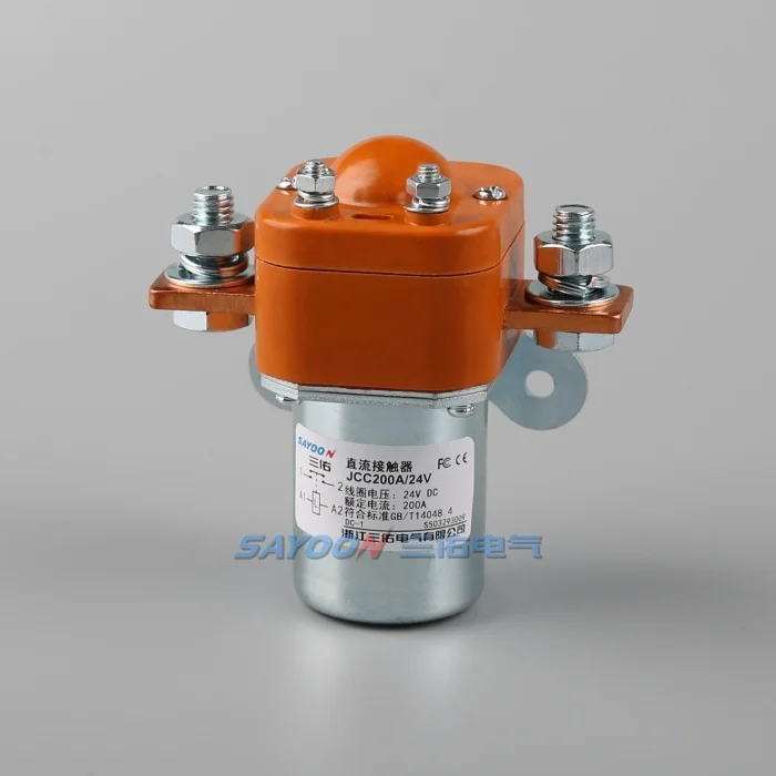
The JCC200A normally open DC contactor is the real Sayoon construction reference illustrated here. Its image does not establish the hypothetical current values, a peak demand, or approval for this application. Request the exact ordering-code documentation before choosing its coil variant. Link the final evidence to the drawing and software revisions, so later substitutions or changes in simultaneous operation trigger a fresh budget review.
Educational video
The Electrician U introduction distinguishes the coil circuit from the main contacts. That distinction helps define the control-power boundary, but the video does not calculate a shared supply budget or approve a particular product. Use it as background alongside the written method and exact equipment documentation.
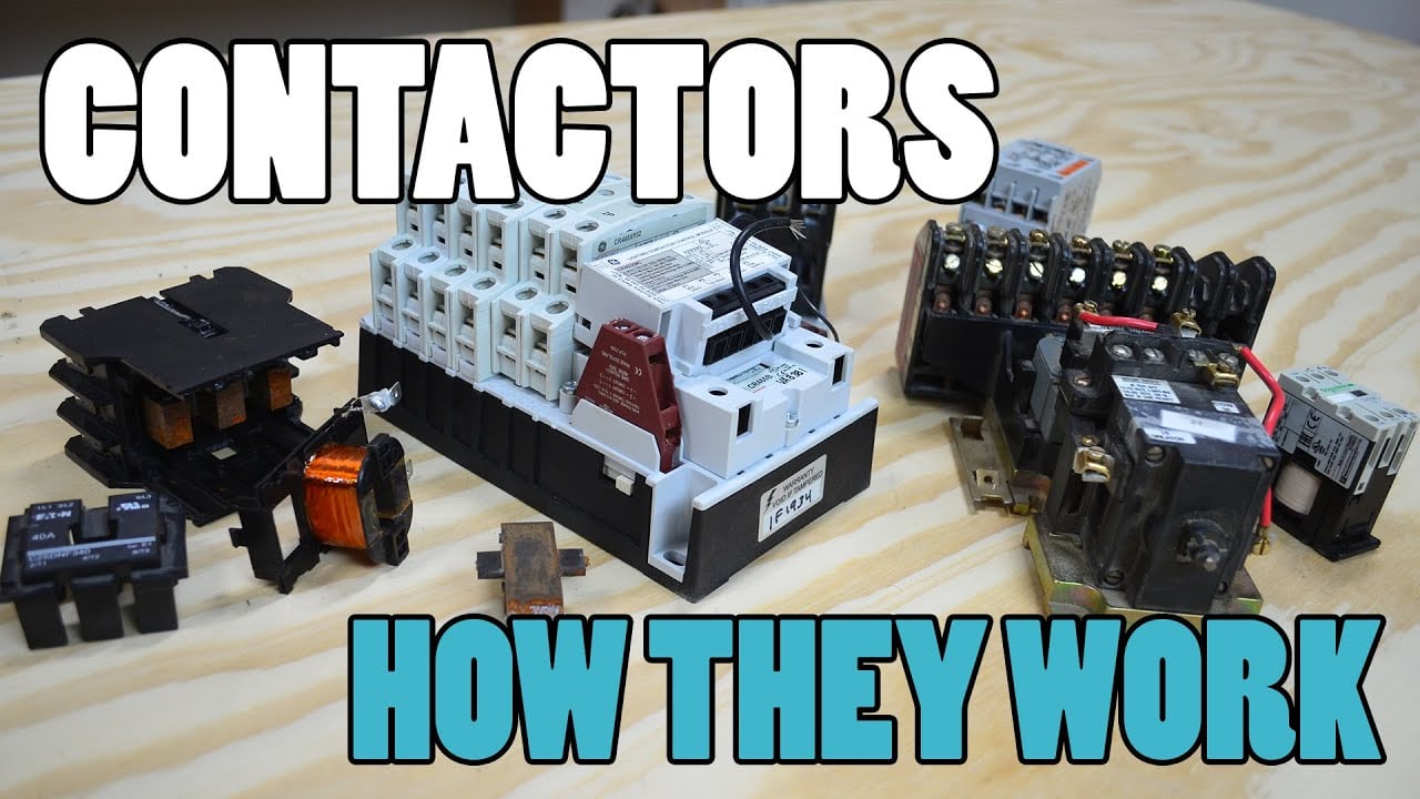
Watch the Electrician U educational introduction.
Frequently asked questions
Can I size the supply by adding hold watts?
That is only the continuous-load starting point. Also check the overlapping demand waveform, terminal voltage, temperature conditions, and overload response.
Does every DC coil have high inrush current?
No. Obtain the exact coil and driver data. Plain windings, internal electronics, and economized designs can have different demand profiles.
Is a larger power supply always sufficient?
No. Wiring loss, driver limits, overload behavior, startup timing, and equipment voltage limits still need review.
Can sequencing reduce the required peak current?
Yes, when the sequence reliably prevents overlapping demand in every relevant operating and restart mode. Document and verify that assumption.
Related engineering reviews
Use the DC contactor selection guide for the complete duty; the coil-current measurement method for individual branch demand; and the coil-voltage tolerance review for the device-terminal check.
Apply the approved electrical isolation procedure before altering the setup. 29 CFR 1910.333 provides a relevant work-practice reference within its jurisdiction; it does not approve this example or replace the responsible test procedure.