A DC bow-thruster contactor must be selected for the actual motor circuit, reversing sequence, battery voltage under load and permitted operating duty. Matching a printed current number is insufficient. A unit can carry the running load yet have unsuitable making or breaking capability, or its control coil can release when the thruster depresses the battery supply. Treat direction switching, battery isolation and equipment protection as separate functions before choosing a replacement.
This guide addresses conventional battery-fed DC thrusters with electromechanical direction control. Electronic drives, hydraulic thrusters and integrated proprietary controllers need their own documentation. The disconnected Sayoon product shown here illustrates construction only; it is not evidence of marine approval or compatibility with any named thruster.
Identify the thruster circuit before comparing contactors
Start with the equipment model, motor diagram and original contactor assembly reference. A permanent-magnet motor and a wound-field motor do not necessarily reverse through the same connections. Changing both field and armature polarity together can preserve rotation direction in some wound-field arrangements. Consequently, a generic drawing copied from a different motor can produce an incorrect replacement even when the terminals appear similar.
Ask whether the proposed component is a complete reversing assembly or one element in a larger circuit. Record the physical terminal positions, the manufacturer’s functional diagram and any factory links separately. A photograph identifies external arrangement; it does not establish the internal switching sequence. Preserve the approved circuit until an equipment-qualified reviewer confirms the replacement.
A main battery disconnect also has a different purpose from a direction contactor. Normal joystick operation need not provide maintenance isolation. Conversely, a disconnect must not be assumed suitable for repeated directional commands. Identify which device is expected to interrupt current during a control fault, and which protective device clears a short circuit.
Understand why loaded battery voltage matters
A battery can show an apparently healthy resting voltage and still produce an unacceptable voltage at the motor during a thruster command. Battery condition, cable resistance, connections and other shared loads all influence the loaded supply. A measurement at the battery posts alone can miss a substantial loss between the source and the bow equipment.
Record voltage at the motor supply and at the contactor coil during the same controlled event. The coil may be powered through a separate control cable, relay, connector or electronic interface. Its voltage therefore need not match the voltage measured on the large power terminals. Interpret each reading against the relevant manufacturer’s limits rather than a universal percentage invented for all coils.
OpenStax explains the relationship between motor speed, back electromotive force and current. This physical principle helps explain why starting differs from established rotation. It does not supply a thruster’s starting current or a contactor’s interruption rating. Obtain those values from equipment records, suitable measurements and the component documentation.

Separate chatter from a diagnosis
Repeated clicking during a command is a symptom, not proof that the contactor itself is defective. A supply disturbance can release the coil; opening the motor path can allow voltage to recover; the continuing command can then energize it again. Other possible causes include a control fault, poor connector, unsuitable coil or a mechanical defect. Several causes can produce similar sounds.
Do not keep issuing commands merely to reproduce the noise. Repeated switching can worsen contact wear and heating, while vessel movement and propeller hazards remain present. Establish a controlled inspection plan and use the equipment’s isolation procedure before checking connections or moving components. Live recordings require qualified personnel and equipment suited to the available electrical energy and environment.
After an intervention, compare the before-and-after evidence. If a repaired cable joint restores coil voltage and stops chatter, record that result without claiming every internal contact is undamaged. An earlier abnormal switching event can justify further inspection under the component manufacturer’s criteria.
| Review item | Evidence to collect | Selection implication |
|---|---|---|
| Motor command | Motor type and approved direction circuit | Do not infer reversal wiring from terminal count |
| Battery under load | Battery posts, motor terminals and coil voltage recorded separately | Separate source sag from control-path loss |
| Opposite direction request | Release/current conditions required by thruster instructions | Preserve documented reversal inhibition |
| Short-burst duty | Starts, reversals, duration and thermal limits | Check motor limits separately from contactor ratings |
Reversal needs a documented permission sequence
An opposite joystick command does not by itself prove that the motor is ready for reversal. The previous current path must be released, and motor motion and current must satisfy the equipment’s permitted conditions. Mechanical coast-down, electronic inhibition and auxiliary feedback may each contribute, depending on the design.
Never assign a universal reversal delay from an unrelated contactor catalog. A time adequate for one installation can be inadequate for a different propeller, motor or supply. Ask the thruster manufacturer how opposing commands are handled and whether an interlock belongs in the contactor assembly, controller or both. A replacement must preserve that division of responsibility.
An auxiliary contact is evidence of its own defined state. Unless its relationship to the main contacts is explicitly documented, it is not a guarantee that the power path is open. Likewise, a software command indicating OFF does not prove that current has ceased. State clearly which signal grants the next operating permission and how a disagreement is detected.
Compare operating duty with switching duty
A thruster may be operated in short bursts, but that does not make every contactor with a sufficient continuous current suitable. Repeated starts, frequent reversals and interruption at different motor speeds create a different duty from uninterrupted carrying current. Evaluate the number and type of operations as well as the duration of each command.
The motor’s thermal restrictions and the contactor’s thermal limits are separate. A contactor that remains within its temperature allowance cannot extend the thruster motor’s permitted operating time. Conversely, staying within the motor’s time limit does not prove acceptable contact erosion or terminal temperature in a replacement assembly.
Prepare an operating description that distinguishes first start, established rotation, normal stop, attempted reversal and an abnormal event. For each, identify the current and voltage information available and the missing evidence. Request component ratings applicable to those events rather than converting a general ampere label into an unsupported application claim.
Review the marine installation environment
Moisture, salt contamination, vibration, access restrictions and nearby equipment can influence the installed assembly. A component’s visible metal finish does not demonstrate corrosion performance. Nor does an enclosure automatically provide the necessary environmental protection once cable entries, ventilation and service openings are considered.
The UK Maritime and Coastguard Agency’s engineering guidance highlights electrical installation and maintenance considerations. Use it as general context, then identify the current rules applicable to the vessel, its flag, class and operating area with the responsible professional. This article does not establish regulatory compliance for a component or installation.
Record mounting orientation, clearances, cable support and maintenance access from the manufacturer’s instructions. Large cables should not impose unreviewed mechanical loads on terminals. Tightening methods and torque values belong to the exact hardware documentation. A photograph of a similar unit is not a basis for inventing a tightening value.
Build a useful replacement enquiry
Send the supplier the equipment reference, motor type, circuit drawing, actual system voltage range, coil supply details and operating sequence. Include original component markings, installation dimensions, cable termination details and any environmental requirements. Explain whether the enquiry concerns a complete reversing assembly, an individual switching device or a battery disconnect.
Describe the fault with observations rather than conclusions. For example, report that the coil voltage fell during a command and the assembly clicked repeatedly; do not simply ask for a stronger contactor. Include the measurement location, test conditions and whether the vessel was safely restrained under the approved test plan.
Ask for the proposed model’s current documentation, making and breaking conditions, thermal duty, coil limits, suppression arrangement and any required interlocks. Request explicit confirmation of unresolved application questions. A supplier’s dimensionally similar alternative should remain a proposal until the equipment owner or qualified integrator accepts the complete comparison.
Validate the assembly and retain the evidence
Acceptance should use an agreed commissioning plan for the vessel. Verify the installed identity and connections against the approved drawing before energization. Then assess normal commands, stopping, direction inhibition and documented fault responses using safe, controlled conditions. Do not create a short circuit, obstruct a propeller or force a motor stall as an informal test.
Retain the circuit revision, component data, measurement records and the person responsible for acceptance. Include settings and interlock behavior, because a future replacement can otherwise reproduce only the hardware while losing the control assumptions. Note any limits that were not tested and how those limits remain controlled.
A successful brief functional test demonstrates only the conditions actually exercised. It does not establish long-term contact life, salt resistance or every fault response. Those claims require their own evidence. A clear handover identifies what was verified, what relies on manufacturer documentation and what remains subject to inspection or maintenance.
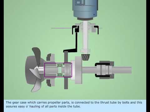
Educational video
This marine training overview illustrates the bow-thruster context. It does not establish a replacement circuit or a contactor rating.
Frequently asked questions
Can I choose a bow-thruster contactor from motor power alone?
No. Power does not establish the motor circuit, loaded voltage, starting current, interruption conditions, reversal sequence or coil requirements. Use the equipment drawing and application-specific ratings together with the operating duty.
Does repeated clicking prove the contactor is worn out?
No. Supply sag, control wiring loss, an unsuitable coil and mechanical faults can produce similar symptoms. Record coil voltage and relevant control states under an approved diagnostic plan before assigning a cause.
Can a reversing contactor replace the battery isolator?
Only if the equipment documentation explicitly gives it that function and the complete arrangement meets the relevant requirements. Direction control should not automatically be treated as maintenance isolation or short-circuit protection.
Is the pictured Sayoon assembly approved for my vessel?
The picture establishes external appearance only. Request the exact model’s current documentation and an application review covering the thruster circuit, duty, environment and applicable vessel requirements before selection.
Product documentation and complementary guides
Use the CZQH150A-2T external-construction reference to discuss physical arrangement with Sayoon, and request current application-specific documentation before selecting it. Start with the DC contactor selection guide. Complementary subjects include Salt Spray Resistance for Marine DC Contactors, How should teams specify a DC reversing contactor on AGV and forklift motor paths?, DC Contactor Drops Out During Engine Cranking.
Primary references and scope
The sources support the underlying physical or application principles described above. They do not establish a rating, certification or application approval for the pictured contactor.