How to test a DC contactor starts with a safe, controlled condition and a clear question: is the suspected problem in the coil command, the mechanical movement, or the current path? A multimeter can help separate those paths, but it cannot certify a contactor or replace the model datasheet, the panel drawing, or the site’s energy-control procedure.
Testing is therefore a sequence of observations. Isolate the equipment, identify the terminals from the actual drawing, compare the expected contact state with the observed state, and record the result with the model and circuit context.
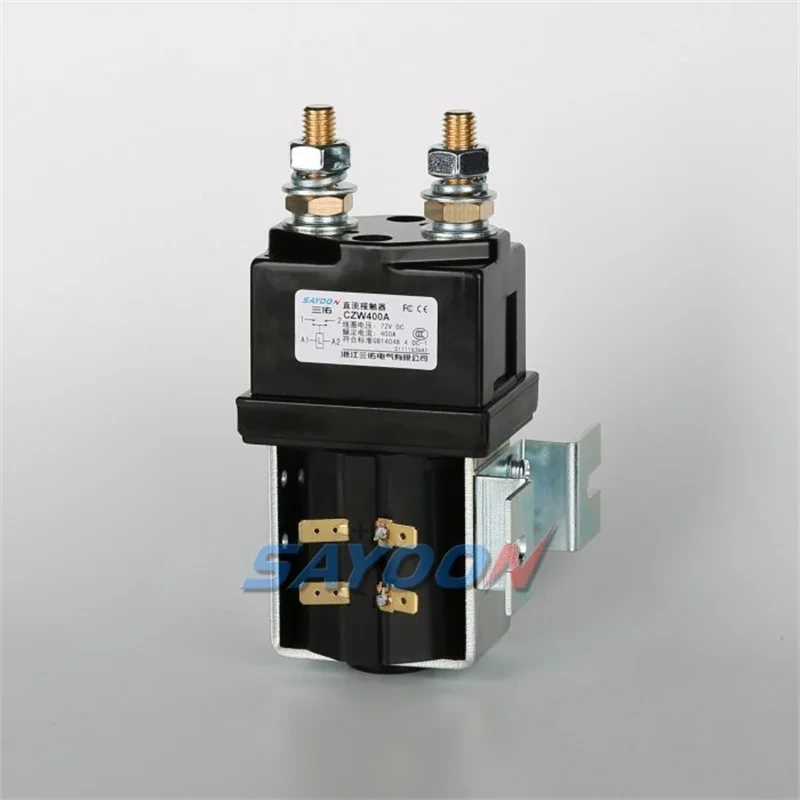
Part 1. What should be isolated before a DC contactor test?
Start with the equipment’s approved energy-control procedure, not with a meter probe. OSHA’s energy-control and electrical-work-practice rules illustrate why servicing starts by controlling hazardous energy and verifying the safe condition; the applicable procedure, competent-person requirements and local rules remain the responsibility of the site. (OSHA energy control, OSHA electrical work practices)
Before opening a panel, identify every source that can energize the contactor path: the control supply, the main DC source, stored energy in connected equipment, and any auxiliary feed shown on the drawing. Mark the test boundary so that a reading is not taken across an unexpected parallel path.
Important: Do not treat a contactor cover, open handle or inactive command signal as proof that the circuit is safe. Begin the diagnostic process only after the site’s isolation and verification procedure has established a safe working condition. Source: OSHA electrical work practices, listed in References.
Part 2. Which test question should the circuit drawing answer first?
Use the drawing to decide what failure you are trying to distinguish. A contactor that does not move, a contactor that moves without carrying current, and a contactor that remains conductive when it should open are different investigations. Starting with a vague “is it bad?” question produces ambiguous readings.
Record the terminal names actually used in the design, then identify the expected normal state of each path. The coil circuit receives a command; auxiliary contacts report or interlock; main contacts carry the intended load path. A service record should preserve the model designation, revision of the drawing, observed command state and the location of the measurement.
| Test question | Drawing detail to identify | Why it changes the next check |
|---|---|---|
| Does the device pull in? | Coil terminals and control source | Separates a command-path issue from a contact-path issue. |
| Is the load path open when it should be? | Main terminals and NO/NC arrangement | Prevents testing the wrong pair of terminals. |
| Is an interlock reporting correctly? | Auxiliary-contact designation | Avoids using an auxiliary indication as proof of main-contact condition. |
Part 3. How do coil, auxiliary and main contacts differ?
The coil is the actuator path. Its test is about whether the winding and its command circuit are being evaluated against the correct model information. The main contacts are the power path. Their state must be interpreted as normally open or normally closed for that design, not assumed from a generic diagram.
Auxiliary contacts serve signalling or interlocking functions. They can support a diagnosis, but their position does not automatically prove the condition of every main pole. Readers who need to decode the contact-state language can review SAYOON’s NO and NC contact configurations before interpreting a meter result.
This distinction matters because a result can be internally consistent yet answer the wrong question. For example, a working auxiliary signal may confirm a control event while leaving the main-current path unproven. Conversely, a discontinuity on a main path is not enough to declare a coil faulty.
Part 4. What can an unpowered meter check show?
With the safe condition established, an unpowered check can compare observed continuity or resistance behaviour with the intended resting state on the drawing. It is a screening step: document which pair was measured, whether the coil was commanded or uncommanded, and whether the result matched the expected state.
Do not publish or reuse a generic “good” resistance number. Coil resistance depends on the exact coil design, and an acceptance threshold for main contacts depends on the relevant model documentation and measurement method. A reading without those references should be logged as an observation for engineering review rather than used as an approval decision.
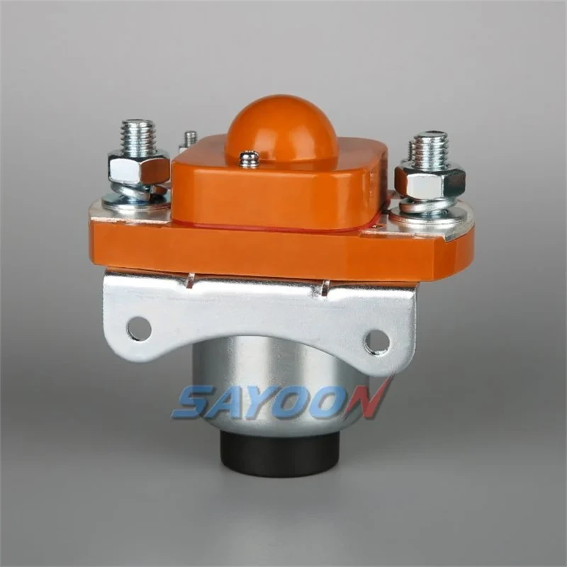
| Observation | What it can support | What it cannot establish alone |
|---|---|---|
| Coil path does not match the expected drawing state | A reason to inspect the coil circuit and model data | A replacement coil value or root cause. |
| Main-contact state does not match NO/NC expectation | A reason to stop and investigate the contact mechanism and circuit | The current-carrying capability of the assembly. |
| Auxiliary state differs from the drawing | A reason to inspect interlocks and terminal identification | The condition of all main contacts. |
Part 5. What should be checked only under a controlled functional test?
A functional test concerns commanded movement and the response of the intended circuit. It should be planned around the actual panel procedure, suitable instruments and the drawing, because the control supply, source condition and connected load can all change what a result means.
Observe whether the command reaches the correct coil terminals, whether the device changes state as expected, and whether the associated indication follows the intended logic. If the contactor chatters, fails to move, or shows a state that conflicts with the drawing, stop the test and preserve the evidence rather than repeatedly cycling the device.
The search results for this topic repeatedly focus on isolating the device, checking the coil and checking the contact state. That is useful as a diagnostic order, but it is not a substitute for a model-specific test instruction or a live-work authorization.
Part 6. When is a continuity result not enough?
Continuity tells you that the meter detected a path under that test condition. It does not tell an OEM whether the device is suitable for the intended current, voltage, switching duty, temperature, command environment or service life. Forum discussions about welded contactor test and detecting an open/closed state show why practitioners ask for more than a single reading: they are trying to distinguish a signal from a trustworthy release decision. (EEVblog discussion)
Treat a mismatch between the drawing and the observed state as a stop condition. Record the configuration, photos permitted by the site, terminal identification and the sequence that produced the result. That package is more useful to a design or supplier team than a statement that the contactor “tested bad.”
For a focused review of a suspected control-side issue, see the related coil-failure checks for OEM service teams. It addresses a different failure question and should not be used to infer a main-contact rating.
Part 7. How should an OEM prepare a replacement enquiry?
When a replacement or design review is needed, use the diagnostic record to narrow the request. SAYOON’s DC contactor product range includes low-voltage product paths such as the CZW DC contactor line and SZJ DC contactor line. Those links support product discovery; they do not make a model recommendation without the application inputs.
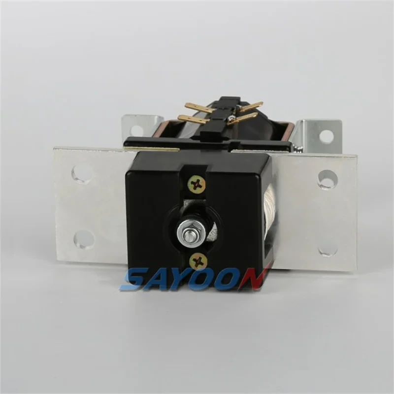
| RFQ input / Buyer should provide | Why it matters | Avoid this shortcut |
|---|---|---|
| Model marking and clear terminal photos | Connects the request to the actual contact arrangement | Selecting by current label alone. |
| Circuit diagram and contact-state requirement | Shows whether NO, NC, auxiliary or interlock paths are involved | Treating an auxiliary contact as a main-contact substitute. |
| Coil-command information and application description | Lets the reviewer identify the control-side question | Guessing a coil option from an unlabelled reading. |
| Test observations and the condition when measured | Makes the diagnostic result reviewable | Calling a continuity check a full acceptance test. |
The fit boundary is simple: do not choose a replacement from a continuity reading alone. When the drawing and application details are ready, send the circuit details for review so the contact form, coil command and application context can be checked together.
FAQ
Can a multimeter test a DC contactor?
A multimeter can support a controlled diagnostic by checking expected coil and contact states after the equipment is safely isolated. It cannot, by itself, certify a contactor for a particular application or replace model documentation.
What coil value should be expected?
Use the exact model’s documentation. This guide does not provide a generic coil-resistance value because different coil designs require different reference information.
How do NO and NC contacts change the test?
They define the expected resting state. Identify the actual contact designation on the drawing before deciding whether an observed open or closed reading is abnormal.
Why can a contactor stay closed?
An unexpected closed state requires investigation of the mechanical contact state, the circuit arrangement and the diagnostic conditions. Do not force it open or assume that a single measurement establishes the cause.
Can the contactor be tested while live?
Live functional work carries additional hazards and must follow the site’s approved procedure, competent-person requirements and applicable rules. Begin with controlled isolation unless the responsible site procedure specifically governs another method.
What should accompany a replacement request?
Include with the RFQ the model marking, circuit drawing, contact-state requirement, coil-command information, application description and recorded test observations. That gives an engineering reviewer a defined basis for the next selection step.





