PLC output test pulses can briefly change the voltage delivered to a contactor coil even when the normal command appears steady. Determine whether the module applies short energizing pulses in the off state, short interruptions in the on state, or another documented diagnostic pattern. Then assess the exact coil, driver, suppression, wiring and feedback response against the module’s requirements. Do not disable diagnostics, add capacitance or assume that average coil voltage proves compatibility. A pulse that seems harmless in one operating condition can have a different effect during pickup, warm operation or a fault response.
Identify the output and its diagnostic function
Obtain the exact controller or output-module code, configuration, firmware and connection diagram. A standard transistor output, a safety-related output and an external interface driver may have different diagnostic behavior. Record which test function is enabled and which channels or groups share its settings. Do not infer the pulse pattern from a generic description of digital outputs.
Separate the normal application command from the electrical output and the module’s internal readback. The program can request on while a diagnostic operation briefly changes the terminal voltage. Conversely, a short voltage event can appear while the application requests off. The relevant documentation should explain the permitted loads, timing definitions and fault handling for the selected configuration. Keep those definitions in the compatibility record.
Distinguish on-state interruptions from off-state pulses
An on-state test can briefly interrupt an energized output to check its behavior. Whether the actuator reacts depends on the complete electrical and mechanical response, including current decay and any electronics. An off-state test can briefly apply voltage to an otherwise de-energized load. These two situations create different questions and should not be grouped into a single average reading.
Names such as light test or dark test are used in some product documentation, but terminology and implementation vary. Use the exact module definition instead of transferring another manufacturer’s label or timing. Also distinguish deliberate diagnostic pulses from leakage current, PWM coil control, supply ripple and an unstable application command. Similar-looking waveforms can require very different corrections.
Define the system states that need compatibility
Review pickup, established hold, normal release, restart, power restoration and the required fault response. A coil that ignores a short pulse while cold and fully released may behave differently when the mechanism is already moving. A driver with internal electronics may also interpret a pulse differently from a plain winding. Obtain the exact coil-option and interface information before interpreting the event.
Include the other loads and channels that can operate together. Shared return impedance or a source disturbance can combine with diagnostic activity and alter the delivered voltage. Record whether the module tests channels independently or according to a documented group sequence. Do not accept a normal steady hold test as evidence that every permitted startup and restart condition is compatible.
Measure terminal voltage, current and command together
Capture the output command, voltage at the coil terminals and coil current on an appropriate timebase. Add documented feedback where it helps identify a mechanism-related response. State the measurement reference and instrument settings. A slow controller trend or handheld meter may average over the diagnostic event and make the output appear stable.
Use a suitable differential or isolated measurement arrangement where required by the circuit. Do not attach an earth-referenced scope ground to an arbitrary switched coil terminal. The qualified test owner must establish safe connections and control stored energy in the main circuit. Preserve raw captures so another engineer can inspect pulse duration, repetition, polarity and the surrounding operating state.
Understand why voltage and actuator response differ
For a plain inductive winding, current changes according to the applied circuit conditions rather than instantaneously following every voltage edge. Resistance, inductance and suppression affect that response. Internal economizers, rectifiers or electronic drivers can change the relationship further. Therefore a visible voltage pulse does not automatically mean that the armature moved, while an average current reading does not prove that no significant event occurred.
Observe the actual current waveform and the response relevant to the system requirement. Avoid calculating a universal safe pulse duration from nominal coil resistance alone. The mechanism, temperature, supply range, driver strategy and manufacturer limits all matter. If the required compatibility information is unavailable, request written evidence or a defined validation method instead of assuming that all contactors filter short pulses naturally.
Review suppression and output readback together
A suppression network changes how inductive current decays and where energy is managed during switching. Depending on the arrangement, it can also affect the voltage observed by the output module during a diagnostic event. Confirm the internal and external components and the exact driver topology. Do not add another suppressor without checking whether the module or coil already includes one.
The module’s diagnostic readback and the actuator response both need to remain within the approved combination. Solving a nuisance diagnostic message by changing the load can alter release behavior or mask a wiring fault. Likewise, adding a capacitor to hold the coil through interruptions can increase capacitive demand and change the readback conditions. An apparently quieter waveform is not complete evidence of a valid interface.
Consider off-state energy and unintended response
For an output that tests while off, review whether the pulse produces coil current, charges internal electronics or interacts with another circuit. A measured open-circuit voltage is not the same as the voltage and current delivered to the actual connected load. Establish the real load condition and preserve the polarity and return arrangement in the record.
Watch for unintended mechanism movement, misleading feedback transitions or repeated charging of an electronic input, as applicable to the exact product. Do not demonstrate compatibility by repeatedly pulsing an actuator attached to an uncontrolled machine. Establish a safe test state and approved method. The system must retain its required behavior when an output is commanded off, not merely avoid a visible full contactor closure in one bench trial.
Treat diagnostic settings as part of the control design
A configuration setting may offer a timing adjustment or a different permitted test mode. Whether it can be changed depends on the module instructions and the safety or control requirements of the application. Record the reason, original value, proposed change and required verification. Do not select a value simply because it makes the fault message disappear.
For a safety-related function, a diagnostic change can affect the evidence supporting the complete system. Have the responsible designer review the fault detection and response requirements. This article supplies no universal setting and does not authorize disabling a safety feature. Retain the approved configuration with the hardware and software revisions so future service work does not restore an incompatible default unknowingly.
Use a compatibility evidence table
The following qualitative checklist organizes the review. It does not provide a pulse-width limit or approve the illustrated contactor for a specific output. Obtain the exact module, coil and interface documentation to close each row.
| Review | Evidence | Decision |
|---|---|---|
| Output identity | Exact module, firmware and configuration | Use its actual diagnostic definitions |
| On-state interruption | Voltage, current and response during hold | Check intended hold and readback behavior |
| Off-state pulse | Actual connected-load current and response | Check unintended activation or charging |
| Suppression | Internal/external arrangement and release trace | Review diagnostics and actuator response together |
| Parameter change | Documented limits and fault-detection requirements | Do not disable diagnostics as a shortcut |
| Interface proposed | Full signal path and fault behavior | Validate the entire combination |
Evaluate an interface only when it is documented
A manufacturer-approved interface may be appropriate when the direct connection cannot meet the required behavior. Review the output’s permitted load, the interface input, its output duty, isolation where relevant, diagnostic transfer, suppression and failure modes. A relay or driver added between the module and contactor does not automatically preserve the original diagnostics or safety architecture.
Keep the full signal path in the validation plan. The controller must detect and respond to the faults required by the design, and the actuator must still pick up, hold and release correctly. A separate power supply or intermediary component can introduce a different return path or stored-energy condition. Assess the complete arrangement instead of treating the interface as an invisible replacement wire.
Validate across the actual operating envelope
Repeat the relevant off, pickup, hold and release sequences at the permitted supply and temperature conditions using the approved method. Include diagnostic operation and the combinations of channels that the module can exercise. Record both nuisance faults and any unintended actuator response. Use the manufacturer’s test recommendations rather than an arbitrary pulse generator setting.
Retain measured waveforms, configuration exports, device codes, suppression details, wiring revision and the acceptance source. Distinguish a normal operation test from a fault-response test, and state the limits of each. If a sample differs from the production assembly, list those differences. A single successful bench cycle cannot establish the performance of a different cable, driver, coil option or module configuration.
Keep the page boundary clear
This question differs from static off-state leakage and from intentional PWM holding control. The leakage guide addresses residual current when an output is nominally off. The PWM guide addresses deliberate current regulation during operation. Here the primary concern is compatibility with diagnostic events that the controller or output module introduces while checking its own circuit.
Use those related guides to identify adjacent causes without creating a second general coil-fault explanation. If the capture shows only supply ripple or a changing application command, follow that evidence instead of blaming the diagnostic function. A useful investigation can demonstrate that the suspected test pulse is not responsible, provided the relevant states and measurement limitations are documented.
Product reference and supplier inquiry
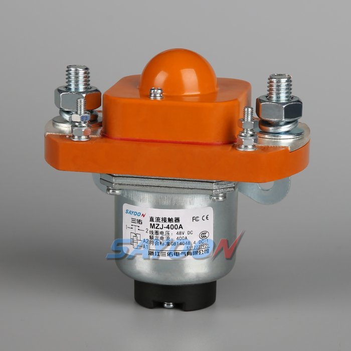
The MZJ-400A normally open DC contactor is the real Sayoon construction reference shown in the illustrations. Its external appearance does not establish compatibility with safety-output diagnostics, a permitted pulse width or an internal suppression arrangement. Obtain the exact coil-option documentation before choosing the interface.
Send the output-module code, configuration, measured terminal voltage and current, command sequence, suppression details, feedback observations and required fault response. Ask which behavior is covered by standard documentation and which requires project-specific verification. A request stating only that the output is a particular nominal DC voltage leaves out the diagnostic pattern that this compatibility review needs to assess.
Educational background: separate coil and main contacts
The Electrician U introduction explains the coil and main-current paths. It supports identifying the circuit boundary; it does not establish product limits or replace the approved procedure for this diagnostic task.
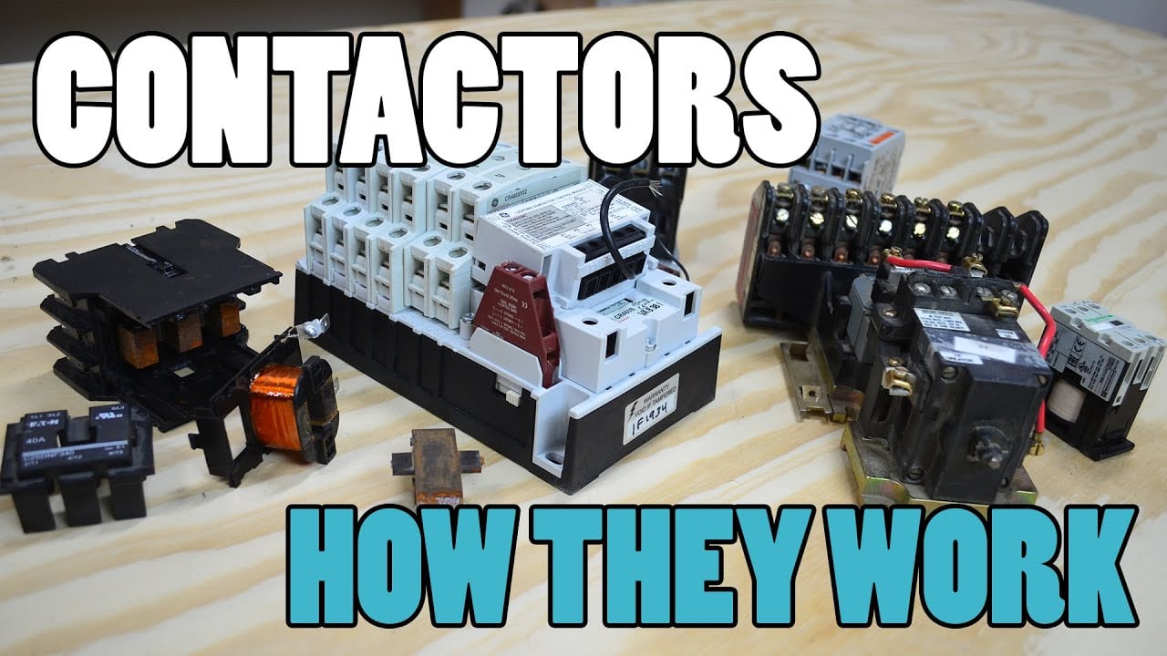
Watch the Electrician U introduction.
Frequently asked questions
Can test pulses exist while the normal command is steady?
Yes, when the exact output module uses that documented diagnostic behavior. Confirm its configuration and electrical waveform rather than relying only on the program bit.
Does a visible voltage pulse prove the contactor moved?
No. Review coil current and the relevant documented actuator response as well as voltage.
Can I add a capacitor or disable diagnostics to stop a fault?
Only through the approved design review. Either change can alter output readback, fault detection, stored energy or actuator response.
Is this the same problem as static output leakage?
No. Diagnostic pulses, static leakage, PWM control and supply ripple are different conditions, although they can interact in the same circuit.
Product and related engineering guides
Request current documentation for the MZJ-400A product reference. Use the DC contactor selection guide for the overall application. Related reviews: off-state coil leakage, PWM holding control, PLC coil-driver interface.
Technical sources and scope
- Texas Instruments inductive-load switching guide: use the stated scope and actual equipment data; this is not approval of the illustrated product.
- Tektronix voltage probing guidance: use the stated scope and actual equipment data; this is not approval of the illustrated product.
- 29 CFR 1910.333 electrical work practices: apply the appropriate jurisdiction and approved isolation method.