Contactor auxiliary contact debounce should reject unwanted short transitions without hiding a real state change or delaying the required fault response. Begin with the raw electrical signal, then account for the exact input module, communication path, controller task and software qualification. Use separate reasoning for the on and off transitions when their requirements differ. There is no universal debounce time suitable for every contactor or PLC. Confirm that the contact load is appropriate, identify wiring noise separately from mechanical bounce, and validate the complete command-to-feedback timing budget before approving a filter.
Define what the feedback signal is used for
A status lamp, a process interlock, an event counter and a safety-related feedback loop do not have the same requirements. State what the controller must recognize, how quickly it must respond and what it should do when the command and feedback disagree. Without that definition, a filter can make the display look stable while degrading the actual control function.
Identify the exact auxiliary contact arrangement and terminal map. A normally open or normally closed label describes a defined state, not a universal relationship to every main contact under every fault. Ordinary feedback, documented mirror-contact behavior and an absence-of-voltage check answer different questions. Keep those limits in the specification rather than allowing software filtering to imply a stronger contact architecture than the product documentation provides.
Inspect the electrical interface before adding delay
Confirm the input voltage, required current, contact load capability, return reference and relevant leakage or diagnostic behavior. An input operating outside the contact’s applicable electrical conditions can produce an unreliable signal that a timer merely conceals. Review the actual module data and contact documentation, including any stated minimum load requirements.
Inspect connectors, terminal identity, conductor routing and common connections. A loose joint or coupled transient may create repeated input transitions long after the contact’s physical movement should have ended. That pattern needs investigation as an electrical fault or installation issue. Do not describe all rapid state changes as harmless bounce, particularly when they occur during established hold rather than at a real commanded transition.

Capture raw and qualified signals separately
Use an appropriate measurement method to observe the auxiliary circuit at a defined electrical point. Align the record with the coil command, relevant current or voltage and the input state reported by the controller. Preserve the actual waveform as well as any processed Boolean trend. A controller log can hide transitions shorter than its update or sampling interval.
Record whether the observed input is raw module data or already filtered by hardware. A software trace labeled raw may still include an input delay that is configured elsewhere. Obtain the module configuration and the task timing. The goal is to locate where the signal changes and where delay is introduced, not to compare two signals whose processing histories are unknown.
Distinguish transition bounce from other faults
A short group of alternating transitions near a physical contact movement can be consistent with bounce, but the observation still requires the correct electrical context. Repeated changes during stable hold may suggest wiring, loading, supply, mechanism or measurement problems. A burst aligned with another device switching can point toward an installation interaction rather than the auxiliary contact itself.
Compare several controlled operations and relevant environmental states. Record whether the pattern is repeatable and which direction of movement produces it. Do not select the quietest cycle as the design basis. If the behavior changes with probe arrangement, investigate measurement pickup before changing the input filter. Suitable probing and reference connections matter even in a nominally low-voltage control circuit.
Understand the hardware input filter
Many input modules qualify a transition according to their own configured behavior. Some require the new state to remain present continuously for a defined interval; others use different internal sampling or filtering methods. On-to-off and off-to-on settings may be independent or grouped. Use the exact manual rather than assuming that all devices implement a parameter named filter in the same way.
Rockwell Automation’s published input-filter guidance illustrates a continuous-state qualification rule and notes that additional circuit delays can remain outside the configured value. That is an example of why the full path must be reviewed, not a setting recommendation for every controller. Record the selected module, firmware, configuration and scope of the setting, especially when changing one channel also changes a group of inputs.
Define software qualification as a state rule
Specify what starts, resets and completes the software qualification. For example, an application may require a candidate state to remain continuously present before accepting it. State what happens if the signal reverses before completion, if the controller changes mode, or if the command changes while a timer is active. An undefined reset condition can leave stale qualification from a previous transition.
Do not assume that counting a fixed number of scans always equals a fixed time. Task execution and data updates have their own timing. Describe the logic in terms appropriate to the actual controller and verify the worst relevant behavior. This article does not prescribe a program or a universal timer value; the requirement is a clear, testable state definition that another engineer can review.
Build a complete timing budget
The observed response can include contactor mechanism timing, contact movement, input-circuit delay, configured filtering, data transfer, task scheduling and application logic. List the stages that actually occur in series for the path under review, and avoid counting the same delay twice. Use documented bounds or validated measurements rather than adding unrelated typical catalog values.
Compare the resulting behavior with both normal-operation and fault-detection requirements. A filter that improves the on transition can still delay recognition of opening. A longer qualification can also mask a persistent disagreement if another timer resets incorrectly. The correct budget should explain which event begins the response requirement and which accepted state or action ends it.
Evaluate on and off transitions independently
A system may need stable confirmation before enabling a load while requiring faster recognition of a loss of feedback. Another application may define different priorities. Determine the requirements from the actual process and safety design. Do not assume that symmetric delay is correct simply because the user interface presents a single familiar debounce value.
For each direction, record the raw transition, qualified state, command and resulting controller action. Include the cases where the feedback changes without a corresponding command. A design that only tests normal pickup and release may miss the response to a disconnected conductor or an unexpected state. The responsible designer should define which fault simulations are permitted and what they represent.
Use a signal qualification review table
The qualitative checklist below organizes the evidence needed for a debounce decision. It does not establish a contactor timing limit or approve a safety function. Match each row to the exact installed devices and the applicable system requirement.
| Review | Evidence | Decision |
|---|---|---|
| Physical contact transition | Raw terminal signal and repeat cycles | Separate bounce from wiring noise |
| Hardware filter | Exact input module and both-edge definitions | Account for module-specific delay |
| Software qualification | Scan, task and state-reset behavior | Avoid hidden delay and stale state |
| Timing budget | Worst relevant path and requirement | Preserve required response time |
| Fault discrimination | Persistent disagreement and diagnostics | Do not filter out a required fault |
| Change validation | Before/after raw and qualified signals | Verify every relevant transition |
Avoid filtering out a fault the system must detect
A recurring disagreement between command and feedback should remain visible until its cause is understood. Do not increase filtering merely to suppress an alarm that may represent an intermittent supply, connector or mechanism problem. Identify whether the filter rejects an unwanted transient or prevents required information from reaching the control logic.
For safety-related feedback, have the responsible designer review the effect of any timing or qualification change on the complete function. A general-purpose debounce pattern does not establish diagnostic coverage or a required performance level. Preserve the approved configuration and verification evidence so service staff do not treat a safety-relevant delay as an arbitrary display preference.
Validate with representative sequences
Test the allowed pickup, hold, release, restart and mode-change sequences with both raw and accepted states recorded. Include the relevant temperature, supply and load conditions that can affect the auxiliary circuit. Use the manufacturer’s instructions and an approved method for any fault-response checks. Do not repeatedly energize an uncontrolled machine to look for the longest bounce event.
Compare before-and-after records using compatible settings. Verify that the signal is stable where required and that a genuine change is recognized within the permitted time. Include the case where a candidate state disappears before qualification finishes. The record should demonstrate the implemented rule, not only show that one nuisance alarm has stopped appearing.
Keep hardware and software changes traceable
Retain contactor and auxiliary-block codes, input-module identity, electrical load, wiring revision, filter settings, controller task information and the software revision. Record the original symptom, measured transitions, acceptance requirement and final disposition. If a contactor or module is substituted, review which parts of the timing and electrical evidence remain applicable.
A replacement with the same terminal count may differ in contact loading, timing or diagnostics. A controller update may change the data path or task interval. Neither should inherit the original debounce approval without review. Clear change records prevent a setting that once matched a specific installation from becoming an unsupported default across several different machines.
Product reference and inquiry
The CZWH100A Sayoon product photograph is the real construction reference used in the illustrations. Its appearance does not establish a debounce interval, input compatibility or a mirror-contact declaration. Request the exact contact arrangement, applicable load information and any documented timing needed for the proposed controller interface.
Send a short raw-signal capture, the module configuration, command sequence, required response time and the conditions under which the symptom occurs. State whether the concern is transition bounce, steady-state intermittency or a disagreement seen only by the controller. That distinction helps the supplier and control designer investigate the actual problem instead of recommending an arbitrary delay.
Educational background: separate coil and main contacts
The Electrician U introduction explains the coil and main-current paths. It supports identifying the circuit boundary; it does not establish product limits or replace the approved procedure for this diagnostic task.
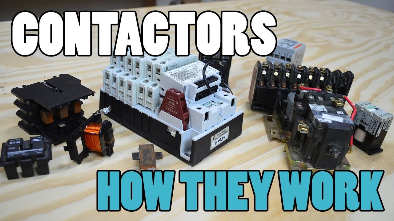
Watch the Electrician U introduction.
Frequently asked questions
Is there a standard debounce time for every auxiliary contact?
No. Use the actual signal, input behavior and complete response requirement to choose and verify qualification.
Does software raw input always mean an unfiltered electrical signal?
No. Module hardware, configured delay and data transfer may already affect the state reported to the application.
Can filtering repair a loose connector or unsuitable contact load?
No. Diagnose the electrical problem rather than hiding its transitions with a longer delay.
Should the on and off transitions use identical settings?
Only if the actual requirements and validation support that choice. Review each direction and its fault-response implications.
Product and related engineering guides
Request current documentation for the CZWH100A product reference. Use the DC contactor selection guide for the overall application. Related reviews: main-contact bounce, auxiliary troubleshooting, feedback timing plausibility.
Technical sources and scope
- Rockwell Automation input filter behavior: use the stated scope and actual equipment data; this is not approval of the illustrated product.
- Tektronix voltage probing guidance: use the stated scope and actual equipment data; this is not approval of the illustrated product.
- 29 CFR 1910.333 electrical work practices: apply the appropriate jurisdiction and approved isolation method.