Solar DC pump dry-run contactor control should remove the permitted motor supply when the approved water-availability or pump-protection logic identifies an unsuitable operating condition, and restore operation only when the documented restart conditions are met. The contactor does not detect water by itself. A selected motor-current value, a low-water probe and a pressure indication represent different evidence, each with limitations that must be considered for the actual pump and installation.
This guide concerns a documented solar-powered pumping system with an appropriate contactor-controlled DC circuit. It does not specify a universal dry-run threshold or authorize placing a contactor between a controller and motor. Follow the pump and controller manufacturer’s instructions for permitted switching locations and protection methods.
Identify the pump and switching boundary first
Establish whether the pump motor is directly supplied, electronically controlled or integrated with a dedicated solar pump drive. A controller may require a defined stop command before its input or output circuit is opened. Another arrangement may use a contactor as part of the approved supply isolation or operating sequence. Those are different duties.
Record the exact pump, motor, controller and source identities. A label such as DC solar pump does not establish motor construction, permissible interruption or the behavior of the controller under varying irradiance. Request the relevant drawings and instructions before proposing a component substitution.
Identify what dry running means for that pump. It may involve insufficient liquid around a required pumping element or another manufacturer-defined condition that can damage the assembly. Do not apply a protection threshold from a different pump type without the required evidence.
Separate low water from other reasons for low output
Reduced water delivery can result from several conditions, including insufficient source water, changing solar input, a blocked intake, a closed flow path or an equipment fault. The expected evidence differs for each condition. A contactor that opens correctly can still be responding to an incorrectly interpreted signal.
A water-level device measures conditions at its installation point. It does not automatically establish water availability throughout the hydraulic path. A flow indication can show movement of liquid at another location, but it may not identify why flow changed. Current or power measurements require an interpretation appropriate to the motor and controller.
Use the pump supplier’s approved protection method and document the signal’s limits. Do not present a generic current-only rule as proof of dry running. Solar variability and electronic control behavior can change electrical readings even when the hydraulic condition has not changed in the same way.
Map the protection and restart sequence
| Review item | Evidence to collect | Selection implication |
|---|---|---|
| Pump arrangement | Pump, motor and controller identity; allowed switching location | Confirm contactor duty and controller compatibility |
| Water evidence | Approved level, flow or electrical detection method | Do not assume one generic current threshold |
| Trip sequence | Protection request and commanded electrical response | Verify the defined stop state |
| Recovery | Water recovery, retry rules and restart permission | A timer or returning sunlight does not prove readiness |
The table provides a qualitative review structure. Thresholds, delays, recovery conditions and acceptance limits must come from the actual pump-system design. Keep the supporting document revision and any commissioning results beside the settings.
Describe normal pumping, low-water detection, controller stop request, contactor operation where permitted, fault indication and restart authorization. Include power loss and restoration. The sequence must explain whether a returning solar supply starts a new evaluation or restores a previous operating request.
Consider the changing solar source
A photovoltaic source and its controller do not behave like an ideal fixed-voltage supply. The available operating condition changes with the installation and environment. Use the controller’s actual specified range and behavior when evaluating coil supply and motor-circuit switching.
A weak supply can create repeated start attempts or unstable contactor holding if the design does not manage it appropriately. Record controller state, contactor command and the relevant loaded voltages together. A panel’s open-circuit reading does not describe the voltage available to the motor or coil during a start.
If a separate control supply is used, identify how it behaves during source transitions and shutdown. Keeping the controller awake while the motor source changes may be intentional, but the design must define what the retained logic permits. Do not add an auxiliary battery or change supply routing without reviewing the complete sequence.
Confirm electrical duty at the permitted location
For a directly connected motor, OpenStax’s explanation of back emf helps distinguish starting from steady running. Actual contactor selection still requires the motor’s current, voltage, inductive duty, start frequency and interruption conditions. A steady running-current measurement is not a complete switching specification.
For an electronically controlled pump, obtain the controller manufacturer’s instructions for contactor placement and sequencing. Input switching, output switching and a low-power enable command can have different consequences. Do not assume a device suitable for one location is acceptable at another.
Ask the contactor supplier to confirm making and breaking duty against the declared circuit. If a contactor is intended only to change state after current has been removed by another device, document that dependency and the response when the expected state is not achieved. Calling it cold switching does not itself prove that every event is current-free.
Choose evidence for water recovery carefully
A low-water condition clearing does not always mean immediate restart is appropriate. The design may require a recovery period, a stable signal, operator acknowledgement or another verified condition. Follow the pump manufacturer’s method and the installation requirements rather than adding an arbitrary universal delay.
A timer measures elapsed time. It does not measure restored water level or confirm that a pump has regained the required hydraulic condition. If time is part of the approved strategy, record the assumptions that make it suitable and the behavior when the next start again fails the protection check.
Avoid endless automatic cycling after a persistent fault. Define the permitted retry behavior and the condition that requires attention. Repeatedly resetting protection to obtain water can increase equipment damage while hiding a blocked source, failed sensor or unsuitable operating condition.
Account for pressure, elevation and unexpected movement
Stopping the motor does not necessarily remove water pressure or prevent flow caused by elevation. The hydraulic design determines the relevant stored energy, backflow and maintenance hazards. Identify the required isolation and verification process for both electrical and hydraulic work.
HSE work-equipment guidance provides a UK-context framework for maintenance, inspection and competence. It does not define a universal solar-pump protection setting. Apply current requirements for the installation and follow the pump, controller and hydraulic-system instructions.
Before accessing equipment, account for automatic restart when light or supply returns. A controller stop command and an open operating contactor are not a complete maintenance isolation process. Identify every relevant source, prevent unintended operation through the approved method and verify the specified safe conditions with competent personnel.
Diagnose a trip with the complete event record
Record water-level or flow evidence, controller status, contactor command, supply behavior and the observed delivery condition. Note time, weather or source conditions where relevant, but do not use weather alone as the diagnosis. The useful record shows which condition changed first.
If the controller requests a stop and the contactor follows it, investigate why the protection logic acted. If the command remains present but the contactor drops out, investigate the electrical control path and supply behavior. A successful contactor replacement cannot validate a low-water sensor or correct a hydraulic limitation.
Preserve the fault record before repeated restarts. Inspect and test only through the approved procedure, with the pump secured as required. If measurements disagree, keep that uncertainty explicit and seek the appropriate supplier information rather than changing several settings together.
Prepare the supplier enquiry and acceptance plan
Provide the pump and controller models, electrical and hydraulic diagrams, solar-source range, intended contactor location, start frequency, protection signal and restart sequence. Include measured switching events where available and identify the actual fault protection. Ask the supplier to state the evidence behind the proposed contactor duty.
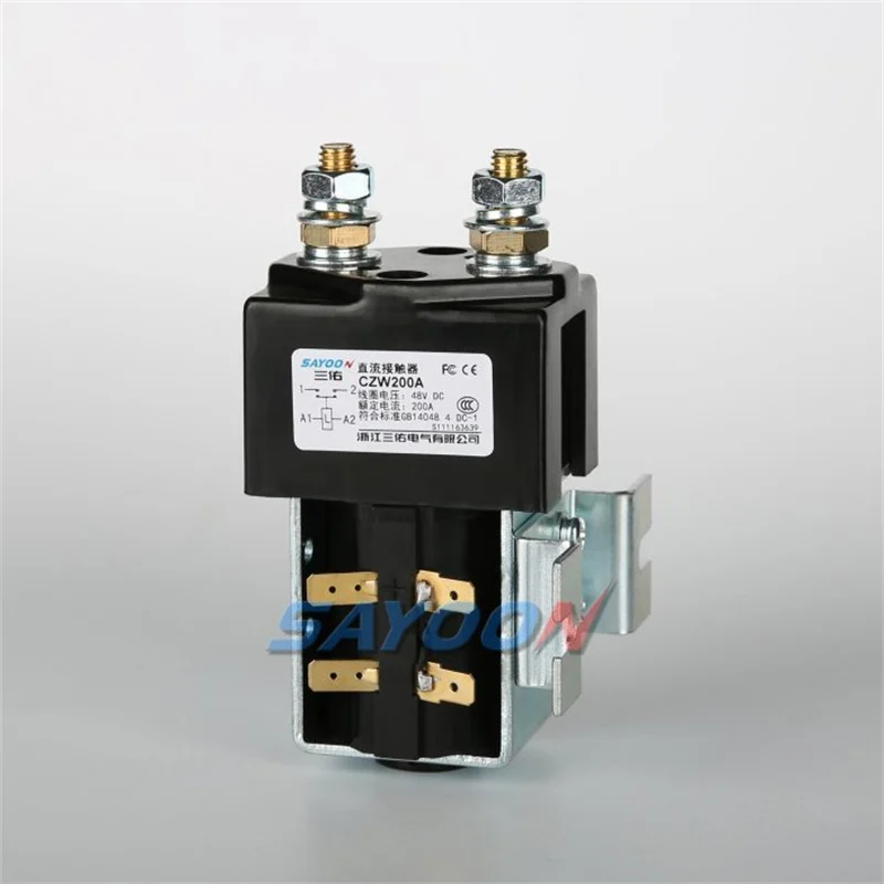
The pictured Sayoon component is an authentic physical product reference for discussing external arrangement. It does not certify a solar-pump application, a dry-run protection function or compatibility with a particular controller. Obtain the application-specific confirmation and preserve any limitations in the engineering record.
Accept the finished system using a documented, manufacturer-approved commissioning method. Do not deliberately damage or run a pump dry to create a test event. Use the prescribed means of verifying protection, then check normal operation, relevant recovery conditions and permitted restart behavior. Keep settings, component revisions and actual results together so future maintenance can preserve the approved logic.
Educational video
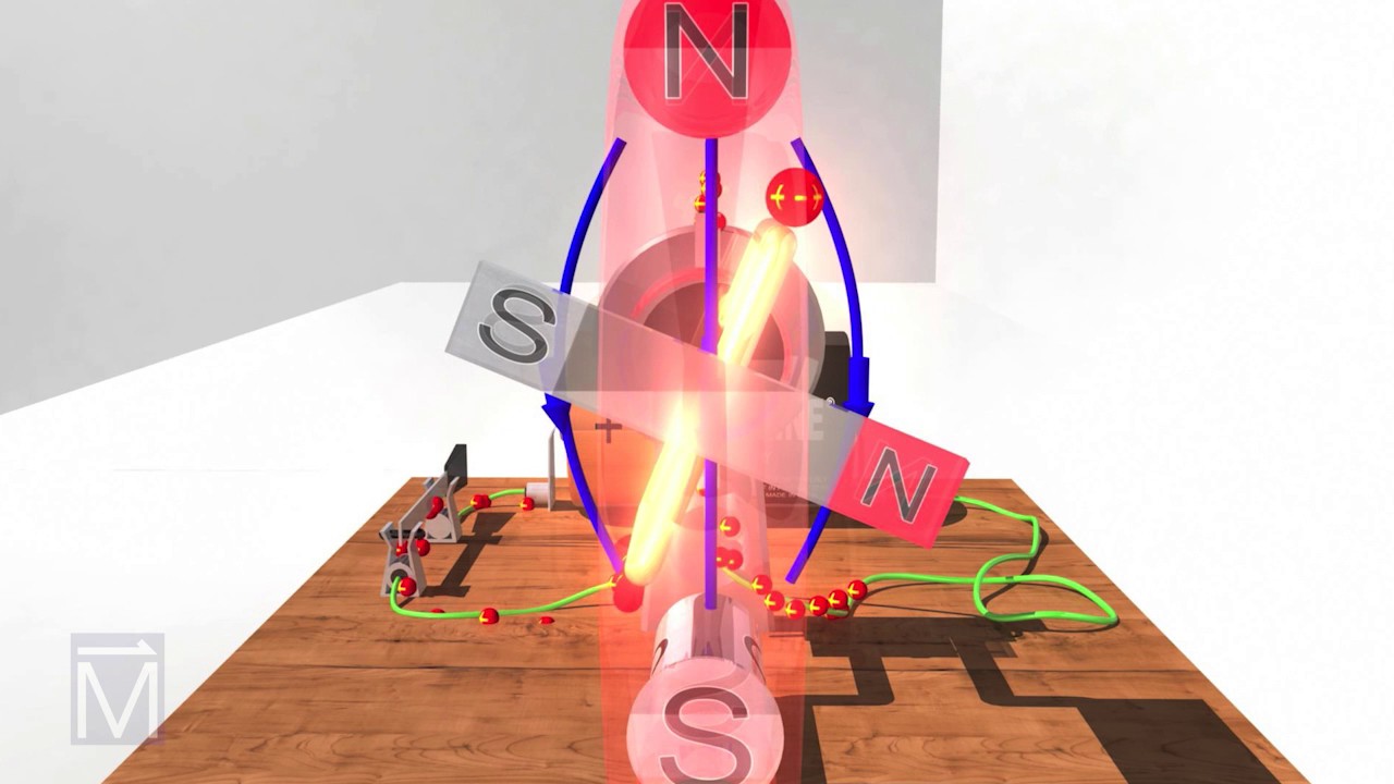
National MagLab explains how a DC motor converts electrical energy into rotation. This section supports the motor principle used in the article; it does not demonstrate the application control sequence, protective function or suitability of the pictured contactor.
Frequently asked questions
Does a contactor detect dry running?
No. It switches a circuit in response to a command. Water-availability or pump-protection logic must supply that command using an approved method appropriate to the pump. The complete system must define both trip and restart conditions.
Is low motor current proof of low water?
Not universally. Motor construction, controller behavior and changing solar input affect electrical readings. Use the pump manufacturer’s approved detection method and validate its interpretation for the installation rather than applying a generic threshold.
Can the contactor be fitted between any controller and pump?
No. Obtain the controller’s permitted switching locations and sequence requirements. Interrupting an output circuit can have different consequences from input switching or using an enable command. Confirm both controller compatibility and contactor duty before installation.
Should the pump restart as soon as the water signal returns?
Only when the documented design permits it and all required recovery and restart conditions are satisfied. A returning signal or sunlight is not automatically sufficient. Follow the manufacturer’s protection strategy and verify the relevant states during commissioning.
Product documentation and complementary guides
Use the CZW200A external-construction reference to discuss physical arrangement with Sayoon, and request current application-specific documentation before selecting it. Start with the DC contactor selection guide. Complementary subjects include DC Contactor Selection for Solar Battery Systems, Forklift Lift-Pump Contactor Selection, How to Diagnose Intermittent DC Contactor Operation.
Primary references and scope
The sources support the underlying physical or application principles described above. They do not establish a rating, certification or application approval for the pictured contactor.