Schnelle Antwort: An EV contactor life calculation should divide the vehicle duty into distinct switching events, apply the manufacturer’s electrical-endurance data at the actual DC voltage and current, account for temperature, inrush, breaking direction, and fault exposure, and then validate the result with representative testing. Mechanical cycle life cannot be substituted for electrical life because arcing and contact heating dominate when load is switched.
Diese Engineering-Anleitung verwandelt das Thema in eine nachvollziehbare Struktur für Batterie-Paket-, BMS-, Test-, Beschaffungs- und Service-Teams. Sie verwendet die reale Produktfamilie als Referenz und hält dabei jede Bewertung und Sicherheitsentscheidung an die endgültige Anwendung und die aktuelle Herstellerdokumentation gebunden.
Entscheidungskarte
| Betriebszustand | Voraussichtliche Beweise | Technisches Schwergewicht |
|---|---|---|
| Normal key-on/off | Low current after correct precharge and torque removal | Largest cycle count; verify sequence remains controlled |
| Charging connection | Bidirectional current and repeated sessions | Voltage window, current direction, temperature |
| Emergency opening | Higher current or abnormal voltage | Separate qualified duty; do not average into normal cycles |
| No-load diagnostics | Mechanism operates with minimal main current | Counts toward mechanical life, not the same wear per cycle |
Produktreferenz und Anwendungsbereich
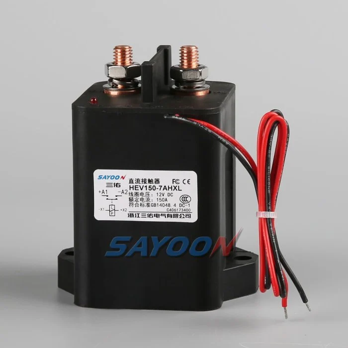
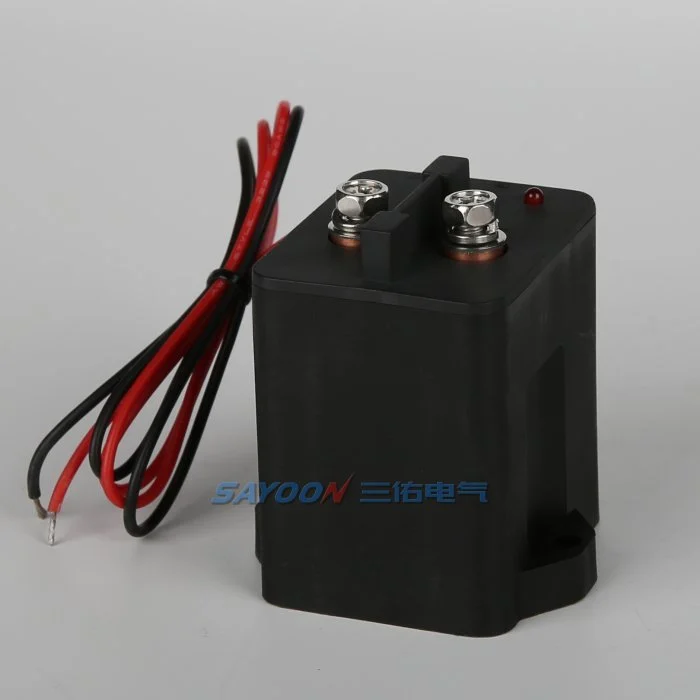
Das HEV150 high-voltage sealed DC contactor Das hier gezeigte Modell ist eine echte Referenz von Sayoon. Lesen Sie die Breite des Hochspannungs-DC-Kontaktoren-Sortiments Für benachbarte Stromklassen. Das Bild und der Familiennamen bescheinigen keine Genehmigung für ein bestimmtes Fahrzeug. Die endgültige Teilenummer, die Spulenoption, das Design, die elektrische Leistung, die Isolierung, die Umweltverträglichkeit, die Lebensdauer und die Schutzkoordination müssen zusammen geprüft werden.
Mechanical life versus electrical life
Mechanical life describes operations with little or no main-contact current under stated conditions. Electrical life describes operations while making, carrying, or breaking a specified load. In an EV pack, the mechanism may survive far more cycles than the contacts can endure under DC arcing. Use mechanical life to check wear from diagnostic exercises and key cycles, but use electrical-endurance evidence for current-carrying events.
The catalogue value is valid only for its test voltage, current, load type, switching frequency, ambient condition, conductor arrangement, and failure criterion. Do not scale it by current alone or assume that half the rated current automatically doubles life.
Build a mission profile
Estimate vehicle years, operating days, trips per day, charge sessions, service events, diagnostic cycles, and abnormal shutdowns. For each event, record whether the contactor makes current, carries current, or breaks current; the voltage and current at the instant of transition; polarity; duration; temperature; and precharge state. Group similar events into bins rather than using one average cycle.
A simple planning total is N_total = years × operating days per year × events per day, but that number is only the start. A life model must preserve the different wear severity of normal zero-current opening, capacitive make, regenerative current, and emergency interruption.
Estimate wear with duty bins
For each validated duty bin, divide the planned number of events by the demonstrated endurance for that exact or conservatively bounding condition. Summing those fractions can be used as an engineering screening index: D = Σ(nᵢ / Nᵢ). If D approaches one, the planned duty consumes the demonstrated endurance. This is not a universal physical law and should not replace supplier data or qualification testing; it is a traceable way to combine approved test points.
Example inputs should come from measured vehicle traces and manufacturer curves. If no endurance point bounds a severe event, mark the result unavailable and request testing. Never invent an Nᵢ value from a nominal current rating.
Precharge and make-current control
Incorrect precharge can dominate contact wear. An inverter DC link initially appears as a capacitive load, so closing the main contactor before the voltage difference is reduced creates a high make pulse. Verify the resistor value, pulse energy, timeout, and measured voltage ratio. Count failed or repeated precharge attempts because they can create more severe events than normal starts.
A contactor that carries 150 A continuously may still be damaged by a much shorter uncontrolled inrush. Separate carry heating from make erosion in the review. The precharge controller should use measured voltage rather than a fixed delay alone.
Breaking current and arc energy
DC current has no natural zero crossing, so voltage, current, circuit inductance, polarity, arc-control structure, and opening speed influence interruption wear. Normal software should remove torque or charging current before opening when the safety concept permits. Emergency opening must be treated as a separate qualified event with its own limit and expected count.
Do not average one high-current break into hundreds of no-load operations. If a crash device or fuse is intended to clear the severe fault, document the coordination and the residual duty the contactor must survive.
Temperature, resistance and installation
Contact heating is related to current squared times resistance. Ambient temperature, enclosure airflow, terminal torque, busbar support, conductor size, and neighboring heat sources change the contact temperature and therefore the life margin. Record contact resistance and terminal temperature on new samples and after endurance blocks.
A rising voltage drop can indicate wear or a loose connection, but the measurement method must exclude cable and joint resistance. Use consistent four-wire points where practical and define the acceptance limit from approved product data.
Validation and confidence
Run representative duty sequences on production-intent contactors, drivers, busbars, and protection hardware. Include cold and hot starts, supply tolerance, vibration, and the switching waveforms that drive the life model. Inspect timing, contact resistance, temperature rise, insulation, and failure modes at planned intervals. Test multiple samples so one favorable unit is not treated as a population guarantee.
Compare measured wear with the calculation, revise the duty bins, and retain the evidence with the vehicle program. Add margin for uncertainty, manufacturing variation, and foreseeable retries.
RFQ data for a life review
Send the battery voltage range, current traces at make and break, continuous duty, switching frequency, event counts, current direction, DC-link capacitance, precharge sequence, fault-clearing strategy, temperature, vibration, mounting, conductor size, coil driver, and target years. Ask the supplier to identify which endurance data applies and what additional qualification is needed.
The HEV150 shown here is a real product reference. Final life approval requires the exact model, coil option, duty, and installation—not a visual match or headline ampere rating.
Akzeptanzrekord
Erstellen Sie einen kontrollierten Datensatz, der die vollständige Teilenummer, die Zeichnungsrevision, die Spulenoption, die Anschlussfunktionen, den Spannungsspektrum, die Stromform, den Schaltzustand, die Details zur Vor- und Entladung, den Treiber und die Unterdrückung, die Hilfslogik, den HVIL-Status, die Schutz-, Umgebungs- und Gehäusetemperaturen, die Montageorientierung, die Details der Leiter und der Busleitung, die Instrumentenpositionen, den Kalibrierstatus, die Softwareversion und die Pass-/Fehlschaltgrenzen enthält. Separaten Messwerten aus den Katalogwerten zuordnen und fehlende Belege als offene Aufgabe markieren, anstatt eine typische Größe einzufügen.
Tests an den entscheidenden Parametern: Niedrige und hohe Spulenversorgung, kalte und heiße Bedingungen, längste zugelassene Länge des Kabelzuges, wiederholte Zyklen und der im Sicherheitskonzept genannten abnormalen Zustände. Erfassung von Befehlen, Spulenspannung und Strom, Hilfserfassung, Packungsspannung, Lastseite-Spannung und Fehlermeldungen auf einer Zeitbasis. Stoppen von automatischen Wiederversuchen nach unerklärlicher Fehlfunktion, Isolierung der gespeicherten Energie und Erhaltung der ersten Fehlerbelegungen. Fotographieren der Einrichtung und des Anschlussplans, Identifizierung aller Messpunkte, Aufzeichnung des Produktionskabel- und Busleitungssatzes sowie eine Erklärung, warum jeder Schwellenwert sicher ist. Nach der thermischen Stabilisierung und dem geplanten Standby-Block wiederholen Sie eine repräsentative Probe. Dazu gehören der Bediener, das Testdatum, die Probenidentität sowie alle Abweichungen von der Produktionsausrüstung. Ein späterer erfolgreicher Test muss keine früheren Fehler beseitigen. Diese Aufzeichnungen ermöglichen die Vergleiche einer Ersatzprobe mit der ursprünglichen, eine Überarbeitung des Lieferantensoftwareprogramms oder einer Änderung des Kabelsets. Ein späterer erfolgreicher Test muss keine früheren Fehler beseitigen. Diese Aufzeichnungen ermöglichen die Vergleiche einer Ersatzprobe mit der ursprünglichen, einer Überarbeitung des Lieferantensoftwareprogramms oder einer Änderung des Kabelsets.
Verwandte Sayoon-Anleitungen
Benutzen Sie Auswahlleitfaden für DC-Schütze, Sicherer Schütztest-Arbeitsablauf, und Zeitplan für Öffnungs- und Schließzeiten für ergänzende Entscheidungen. feedback plausibility guide explains command, auxiliary, and bus-voltage correlation.
Lernvideo
A Look At High-Voltage EV Contactor Technology by CHARGED Electric Vehicles Magazine provides visual background related to this engineering review. It does not replace the written requirements, product data, or vehicle safety procedure.
Sieh dir das Lernvideo auf YouTube an.
Häufig gestellte Fragen
What is the most important check for ev contactor life calculation?
Beginnen Sie mit der maximalen Spannung und der realen Schaltform, überprüfen Sie anschließend gemeinsam die genauen Kontaktdaten, die Steuerungsschema, die Installation und das Fehlverhalten.
Kann ein Hilfskontakt beweisen, dass die Hauptkontakte gesund sind?
Nein. Der Mechanismus der Hilfserfassungsberichte liegt innerhalb seiner Grenzen. Verwenden Sie Busspannung, Zeitsteuerung, Spulenstrom und den Zustand des Schaltkreises als unabhängige Indizien.
Kann eine nominelle Stromstärke als vollständige Auswahlregel verwendet werden?
Nein. Dauerelektrizität, Durchlaufelektrizität, Durchbruchsleistung, Spannung, Temperatur, Polarität, Lebensdauer, Isolierung und Schutzkoordination sind separate Bedingungen.
Welche Informationen sollten bei einer RFQ mitgeteilt werden?
Senden Sie Spannung- und Stromformsignale, Schaltsequenzen, Details zu Umgebung, Spule und Treiber, Rückkopplungslogik, Schutzfunktionen, Montage, Lebensdauerziele und erforderliche Testnachweise.
Zuverlässige Referenzen
- IEC 60947-4-1 contactor and motor-starter standard page
- Texas Instruments high-voltage contactor driver note
- NREL vehicle technologies research
Verwenden Sie die von dem Fahrzeugprogramm festgelegten Ausführungsvarianten und Anforderungen. Normen und Daten der Zulieferer können sich ändern, und das zuständige Engineering-Team muss die endgültige Konstruktion bestätigen.





