Schnelle Antwort: An 800V EV contactor must be selected for the battery’s maximum charged voltage and transients, not the nominal architecture label. It must also satisfy insulation coordination, DC make and break duty, bidirectional current, thermal rise, precharge, short-circuit coordination, coil-driver behavior, feedback diagnostics, environmental stress, and the vehicle’s required switching life.
Diese Engineering-Anleitung verwandelt das Thema in eine nachvollziehbare Struktur für Batterie-Paket-, BMS-, Test-, Beschaffungs- und Service-Teams. Sie verwendet die reale Produktfamilie als Referenz und hält dabei jede Bewertung und Sicherheitsentscheidung an die endgültige Anwendung und die aktuelle Herstellerdokumentation gebunden.
Entscheidungskarte
| Betriebszustand | Voraussichtliche Beweise | Technisches Schwergewicht |
|---|---|---|
| Maximum working voltage | Highest charged pack plus defined operating tolerance | Use model-specific DC ratings and system transients |
| Insulation | Clearance, creepage, dielectric and pollution environment | Coordinate pack, enclosure, altitude and service access |
| Current duty | Traction, regeneration, charging and fault opening | Separate continuous, peak, make and break conditions |
| Schutz | Fuse, pyrofuse, precharge and discharge coordination | Prove fault energy and safe isolation sequence |
Produktreferenz und Anwendungsbereich
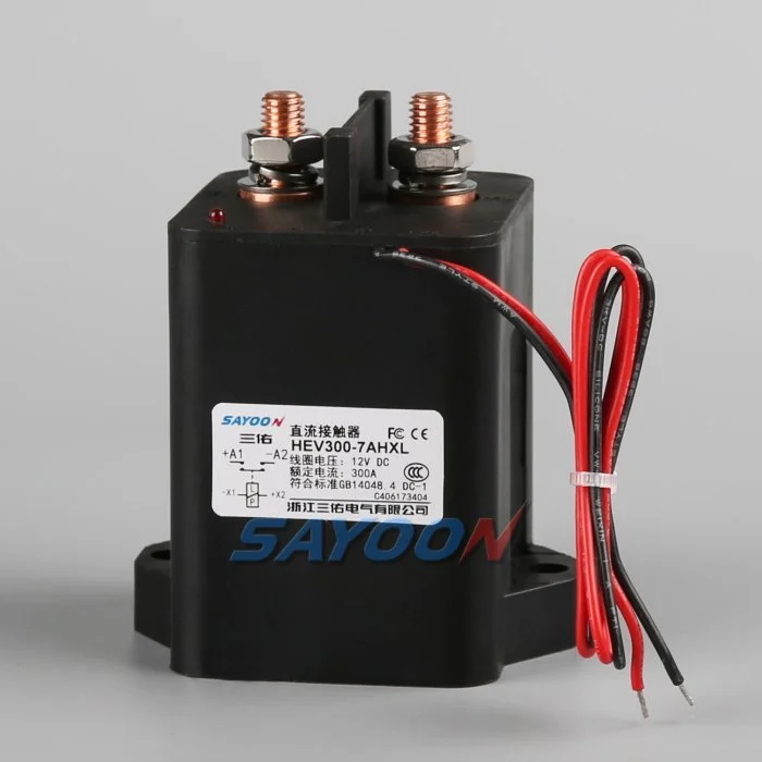
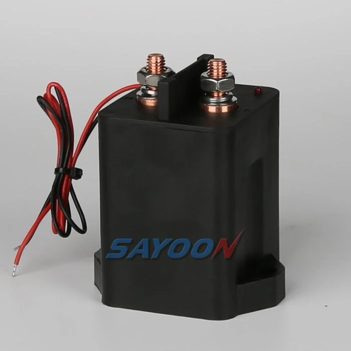
Das HEV300 high-voltage sealed DC contactor Das hier gezeigte Modell ist eine echte Referenz von Sayoon. Lesen Sie die Breite des Hochspannungs-DC-Kontaktoren-Sortiments Für benachbarte Stromklassen. Das Bild und der Familiennamen bescheinigen keine Genehmigung für ein bestimmtes Fahrzeug. Die endgültige Teilenummer, die Spulenoption, das Design, die elektrische Leistung, die Isolierung, die Umweltverträglichkeit, die Lebensdauer und die Schutzkoordination müssen zusammen geprüft werden.
800V is an architecture class, not one fixed voltage
An “800V” vehicle does not operate at exactly 800 V in every state. The pack voltage changes with cell chemistry, series count, state of charge, temperature, and load. Charging and regeneration can place the pack near its maximum charged voltage, while switching transients can briefly add stress. Specify the minimum, nominal, maximum continuous, and defined transient voltages.
Select the contactor using the manufacturer’s approved DC voltage conditions and insulation data. Do not approve a device merely because its name includes 800 V or because an AC insulation number looks high.
Insulation coordination and altitude
Higher voltage increases the importance of creepage, clearance, dielectric withstand, pollution degree, material group, sealing, and the distance to grounded metal. Altitude reduces air density and can require larger clearances or derating. The completed battery junction box—not the contactor alone—must maintain the required insulation under condensation, contamination, vibration, and service conditions.
Review terminal spacing, busbar geometry, mounting hardware, sensors, connector pins, and enclosure ribs. Use the standards and vehicle requirements adopted by the project; do not copy a spacing number without matching the environment and overvoltage category.
DC interruption at higher voltage
A DC arc does not naturally cross zero. At higher voltage, the contactor’s arc-control system, contact gap, opening speed, magnetic field, gas sealing, and current direction become critical. Continuous current and breaking current are different ratings. Confirm make and break performance at the maximum voltage, actual load inductance, and the required polarity or bidirectional condition.
Normal control should reduce inverter or charger current before opening when safe. Emergency opening, crash isolation, and fault interruption require separately qualified duties and protection coordination.
Thermal current and power relationships
For the same power, higher voltage can reduce current, but that does not automatically make the contactor cooler. Fast charging, launch, regeneration, enclosure temperature, terminal resistance, and busbar design still determine heating. Contact loss is approximately I²R, and joint resistance outside the contactor can become equally important.
Use measured current profiles and thermal boundary conditions. Verify temperature rise at the terminals and body with the production busbar, torque, conductor size, airflow, and neighboring fuse or pyrofuse.
Precharge and discharge
The inverter DC link must be charged through a controlled path before the main contactor closes. At 800V-class levels, the stored energy and make-current consequence are substantial. Size the resistor and precharge contactor for maximum voltage difference, capacitance, pulse energy, repeat duty, and temperature. Close the main contactor only after measured voltages meet the approved ratio and timing window.
After opening, verify that the discharge circuit reduces the load-side bus to the vehicle-defined safe threshold. A timer without voltage confirmation cannot prove the bus is safe.
Bidirectional current and charging compatibility
Traction current flows from the battery to the inverter, while regeneration and DC charging send current toward the battery. Confirm that the main contactor carries and switches the required directions. Some 800V vehicles also interact with lower-voltage chargers through a booster or reconfiguration strategy, which can create additional contactor states and switching sequences.
Map each configuration and prevent two contactors from creating an unintended parallel or series path. Add feedback and bus-voltage plausibility checks for every state.
Short-circuit and crash coordination
Define the prospective pack fault current, battery impedance, cable and busbar inductance, fuse or pyrofuse clearing behavior, and the contactor’s required withstand or interruption duty. The contactor is not a substitute for a fuse, and a fuse does not provide repeatable functional switching. The safety concept should state which device acts first and what energy remains downstream.
After a crash event, inhibit reclose, verify isolation and discharge, and require inspection of the contactor, terminals, busbars, fuse, precharge branch, and trigger circuits before service release.
Coil drive, feedback and EMC
The low-voltage coil driver must provide reliable pull-in during supply sag and controlled release during faults. Suppression changes opening time and driver stress. Capture coil current, command, auxiliary feedback, pack voltage, and load-side voltage on one time base. Use independent voltage evidence to detect welded or stuck-open main contacts.
At 800V-class switching levels, layout, shielding, grounding, and measurement isolation affect EMC and diagnostic accuracy. Validate the production harness and controller, not only a short bench setup.
RFQ and qualification checklist
Provide minimum, nominal, maximum and transient pack voltage; continuous and peak currents; current direction; make and break waveforms; DC-link capacitance; precharge and discharge requirements; short-circuit source; protection clearing time; insulation environment; altitude; temperature; vibration; sealing; coil voltage; driver and suppression; auxiliary logic; life; mounting; busbars; and required approvals.
The HEV300 shown here is a product reference. Confirm the exact voltage, current, insulation, coil, and endurance data for the final model and production installation.
Akzeptanzrekord
Erstellen Sie einen kontrollierten Datensatz, der die vollständige Teilenummer, die Zeichnungsrevision, die Spulenoption, die Anschlussfunktionen, den Spannungsspektrum, die Stromform, den Schaltzustand, die Details zur Vor- und Entladung, den Treiber und die Unterdrückung, die Hilfslogik, den HVIL-Status, die Schutz-, Umgebungs- und Gehäusetemperaturen, die Montageorientierung, die Details der Leiter und der Busleitung, die Instrumentenpositionen, den Kalibrierstatus, die Softwareversion und die Pass-/Fehlschaltgrenzen enthält. Separaten Messwerten aus den Katalogwerten zuordnen und fehlende Belege als offene Aufgabe markieren, anstatt eine typische Größe einzufügen.
Tests an den entscheidenden Parametern: Niedrige und hohe Spulenversorgung, kalte und heiße Bedingungen, längste zugelassene Länge des Kabelzuges, wiederholte Zyklen und der im Sicherheitskonzept genannten abnormalen Zustände. Erfassung von Befehlen, Spulenspannung und Strom, Hilfserfassung, Packungsspannung, Lastseite-Spannung und Fehlermeldungen auf einer Zeitbasis. Stoppen von automatischen Wiederversuchen nach unerklärlicher Fehlfunktion, Isolierung der gespeicherten Energie und Erhaltung der ersten Fehlerbelegungen. Fotographieren der Einrichtung und des Anschlussplans, Identifizierung aller Messpunkte, Aufzeichnung des Produktionskabel- und Busleitungssatzes sowie eine Erklärung, warum jeder Schwellenwert sicher ist. Nach der thermischen Stabilisierung und dem geplanten Standby-Block wiederholen Sie eine repräsentative Probe. Dazu gehören der Bediener, das Testdatum, die Probenidentität sowie alle Abweichungen von der Produktionsausrüstung. Ein späterer erfolgreicher Test muss keine früheren Fehler beseitigen. Diese Aufzeichnungen ermöglichen die Vergleiche einer Ersatzprobe mit der ursprünglichen, eine Überarbeitung des Lieferantensoftwareprogramms oder einer Änderung des Kabelsets. Ein späterer erfolgreicher Test muss keine früheren Fehler beseitigen. Diese Aufzeichnungen ermöglichen die Vergleiche einer Ersatzprobe mit der ursprünglichen, einer Überarbeitung des Lieferantensoftwareprogramms oder einer Änderung des Kabelsets.
Also verify labeling, service documentation, isolation points, and change-control approvals before the production design is released to vehicle assembly.
Verwandte Sayoon-Anleitungen
Benutzen Sie Auswahlleitfaden für DC-Schütze, Sicherer Schütztest-Arbeitsablauf, und Zeitplan für Öffnungs- und Schließzeiten für ergänzende Entscheidungen. feedback plausibility guide explains command, auxiliary, and bus-voltage correlation.
Lernvideo
WHAT IS 800-Volt Architecture in EVs? by EV Zone provides visual background related to this engineering review. It does not replace the written requirements, product data, or vehicle safety procedure.
Sieh dir das Lernvideo auf YouTube an.
Häufig gestellte Fragen
What is the most important check for 800v ev contactor?
Beginnen Sie mit der maximalen Spannung und der realen Schaltform, überprüfen Sie anschließend gemeinsam die genauen Kontaktdaten, die Steuerungsschema, die Installation und das Fehlverhalten.
Kann ein Hilfskontakt beweisen, dass die Hauptkontakte gesund sind?
Nein. Der Mechanismus der Hilfserfassungsberichte liegt innerhalb seiner Grenzen. Verwenden Sie Busspannung, Zeitsteuerung, Spulenstrom und den Zustand des Schaltkreises als unabhängige Indizien.
Kann eine nominelle Stromstärke als vollständige Auswahlregel verwendet werden?
Nein. Dauerelektrizität, Durchlaufelektrizität, Durchbruchsleistung, Spannung, Temperatur, Polarität, Lebensdauer, Isolierung und Schutzkoordination sind separate Bedingungen.
Welche Informationen sollten bei einer RFQ mitgeteilt werden?
Senden Sie Spannung- und Stromformsignale, Schaltsequenzen, Details zu Umgebung, Spule und Treiber, Rückkopplungslogik, Schutzfunktionen, Montage, Lebensdauerziele und erforderliche Testnachweise.
Zuverlässige Referenzen
- SAE J1766 electric and hybrid vehicle safety practice
- Texas Instruments nutzt Hochspannungskontakte in Elektrofahrzeugen und Hybridfahrzeugen
- NHTSA electric-vehicle safety information
- Berkeley power electronics technical report
Verwenden Sie die von dem Fahrzeugprogramm festgelegten Ausführungsvarianten und Anforderungen. Normen und Daten der Zulieferer können sich ändern, und das zuständige Engineering-Team muss die endgültige Konstruktion bestätigen.





