Schnelle Antwort: A battery string contactor connects one battery string to a shared BESS DC bus only after the controller proves compatible voltage, polarity, insulation, precharge, and communications. In parallel racks, it also isolates a faulty or serviced string without allowing the remaining strings to back-feed it. Safe operation depends on coordinated sequencing, current-sharing limits, string fuses, voltage sensing, feedback diagnostics, and controlled discharge.
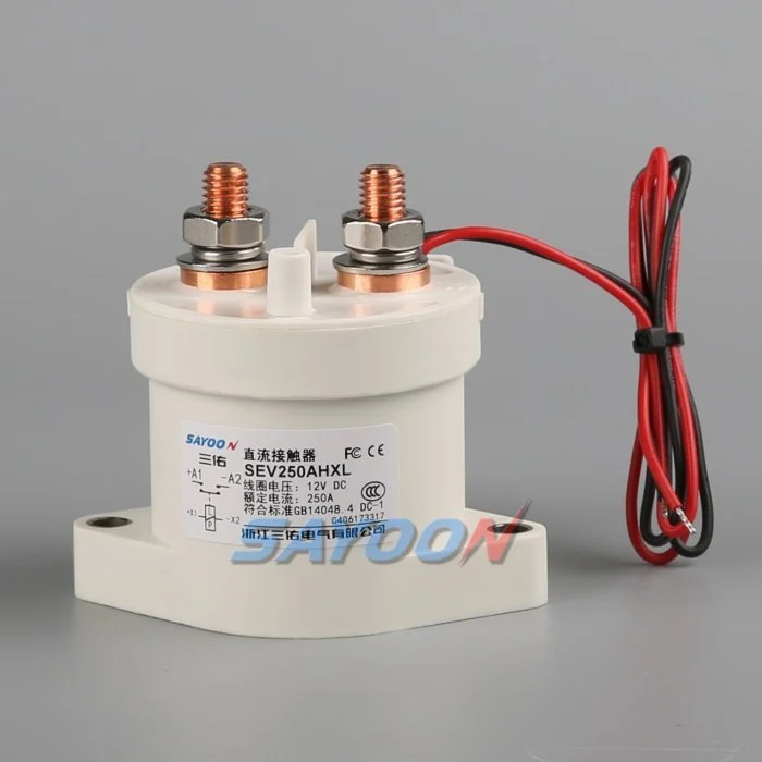
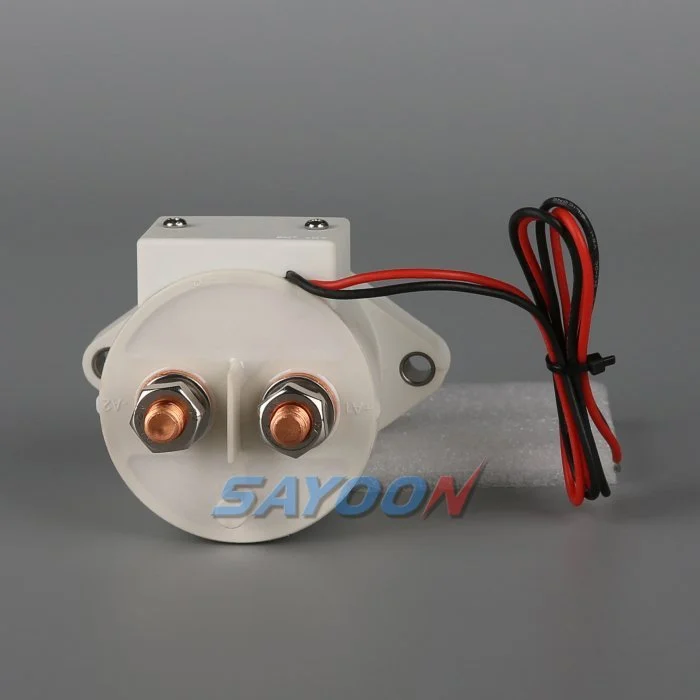
Diese Anleitung verwandelt das Thema in einen nachvollziehbaren Arbeitsablauf für BESS-Entwicklung, Inbetriebnahme und Beschaffung. Dabei wird eine echte Sayoon-Kontaktor-Einheit als visuelle Produktreferenz verwendet, wobei jede Bewertung, Reihenfolge und Sicherheitsentscheidung an das endgültige System und die aktuelle Herstellerdokumentation gebunden ist.
Engineering-Entscheidungskarte
| Systemstatus | Voraussichtliche elektrische Verfassung | Design-Fokus |
|---|---|---|
| String offline | Both mains open; bus may remain live | Prove isolation on both sides |
| Vorentladung | Precharge path active; mains open | Limit equalization current and verify voltage |
| Parallel online | Mains closed after voltage match | Monitor string current and sharing |
| String fault | Affected string opens; others remain controlled | Coordinate contactor, fuse, PCS, and discharge |
Produktreferenz und Anwendungsbereich
Das SEV250AHXL sealed high-voltage DC contactor ist ein relevantes Beispiel für eine relevante Produktfamilie. Lesen Sie die Hochspannungs-DC-Kontaktorenführungen und Auswahlleitfaden für DC-Schütze für den breiteren Arbeitsablauf. Eine visuelle Übereinstimmung oder nominaler Strom genügt nicht als Grundlage für die Auswahl eines BESS-Modells. Zusammengesetzt aus Spannung, Durchflusshöhe, Betriebsdauer, Polarität, Isolierung, Temperatur, Umgebung, Lebensdauer, Montage, Treiber und Schutz.
Why each string needs a controlled boundary
Parallel battery strings share a bus but do not remain identical. State of charge, temperature, internal resistance, cable resistance, and aging change each string voltage and current. A battery string contactor gives the BMS a controlled boundary for startup, fault containment, maintenance, and availability management. It is not a replacement for the string fuse and cannot correct cell imbalance.
The one-line diagram should show positive and negative mains, precharge branch, fuse, service disconnect, voltage and current sensors, insulation monitoring, auxiliary feedback, and the shared PCS connection. Mark every section that can remain energized when a single string is offline.
Match voltage before paralleling
Closing two strings with different open-circuit voltages can create a large equalization current limited mainly by impedance. Before closure, compare string voltage and bus voltage with sensors that have known accuracy and timing. Confirm polarity and communications. Use precharge or another approved matching method where required.
The acceptance window must include sensor error, contactor timing, capacitance, cable impedance, and the BMS strategy. A fixed delay does not prove voltage match. If the bus is outside the approved window, stop the sequence, identify the energizing source, and prevent repeated closure attempts.
Sequence the contactors and precharge path
A typical sequence verifies interlocks and insulation, closes the designated return path, activates precharge, watches bus voltage rise, closes the main path, then opens or de-energizes the precharge branch as designed. The exact order depends on the system. Document the expected voltage and feedback after every step.
On shutdown, reduce PCS current when possible, open the required mains, confirm current stops, and verify the isolated side. The shared bus can stay energized from other strings, so pack-side and bus-side measurements are both necessary.
Manage current sharing after closure
Once parallel, current does not divide perfectly. A lower-resistance or higher-voltage string can take more charge or discharge current. Monitor each string rather than relying only on total PCS current. Set warning and trip logic from validated battery and conductor limits, including sensor uncertainty and transient sharing.
Investigate persistent imbalance through state of charge, cell temperature, contact resistance, fuse and busbar joints, cable length, sensor calibration, and BMS estimates. Do not repeatedly open and close a string to force sharing unless the approved control strategy specifically supports that behavior.
Isolate faults without creating another fault
A string overcurrent, insulation fault, thermal event, communications loss, or contactor mismatch may require isolation. The controller must decide whether to reduce PCS power first, open the affected string, or shut the common bus. Opening under current must remain within the contactor duty and protection concept.
Other strings can feed the fault through the bus until the isolation and fuse sequence completes. Calculate prospective current and clearing energy. Preserve first-fault timing so the team can distinguish a battery fault from a welded contactor, failed driver, or incorrect current sensor.
Detect welded and stuck-open conditions
Compare contactor command, coil current, auxiliary feedback, string current, string voltage, and bus voltage. A closed auxiliary contact does not prove low-resistance main conduction. An open auxiliary contact does not prove that bus voltage has disappeared. Evaluate the complete circuit, including a parallel back-feed path.
After an open command, a persistent current is strong evidence of an unintended path. Similar voltage on both sides may be normal when the shared bus remains energized and the isolated string voltage is close, so use an approved diagnostic stimulus or discharge path rather than voltage equality alone.
Commission strings one at a time
Commission with production-intent racks, busbars, controllers, sensors, fuses, and PCS. Verify polarity, part numbers, drawings, terminal torque, coil supply, suppression, auxiliary logic, and sensor calibration before energizing. Bring one string online through the complete sequence while recording synchronized waveforms.
Repeat for each physical position, then test parallel connection, controlled removal of one string, communication loss, low control voltage, sensor faults, failed precharge, emergency stop, and restart restrictions. Use authorized procedures for hazardous energy and do not bypass interlocks to accelerate testing.
Document the operating envelope
Record the number of strings, battery voltage range, permissible voltage mismatch, charge and discharge currents, transient sharing, current at make and break, precharge capacitance and resistance, fault current, fuse clearing, temperature, enclosure, conductor resistance, switching cycles, coil driver, feedback, and service strategy.
The SEV250AHXL shown here is a product-family reference. Confirm the final part number and product-specific data for the real string duty. Keep calculations, raw waveforms, settings, deviations, and approvals with the as-built configuration.
Manage changes and periodic checks
Review the original evidence whenever cell chemistry, string count, PCS firmware, cable length, busbar, fuse, cooling, sensor calibration, contactor coil, driver suppression, or operating schedule changes. A physically interchangeable part can alter current sharing, pickup margin, release time, or fault coordination. Identify the affected assumptions and repeat the necessary tests.
During maintenance, inspect terminal joints, barriers, conductors, heat evidence, contamination, mounting, control wiring, and diagnostic history. Compare voltage drop and temperature only under comparable current and measurement conditions. After replacement work, exercise the complete approved sequence under representative load and confirm that one isolated string cannot be energized through the common bus or an auxiliary path. Record the reviewer and final disposition.
Sicherheits- und Beweiskontrollen
Behandeln Sie Batterien, übliche Bus- und Konverterkondensatoren, Parallel-Racks, Hilfsmaterialien und Prüfgeräte als gefährliche Energiequellen, bis eine autorisierte Person das Verfahren zur Standortisolierung angewendet und den erforderlichen Zustand mit Messgeräten überprüft hat. Überbrücken Sie keine Rückkopplungsbuchsen, fordern Sie keine Spulen an, deaktivieren Sie HV-Verriegelungen oder öffnen Sie Geräte außerhalb ihrer qualifizierten Schaltfunktion. Ein BESS kann von einer Position betrieben werden, die auf einer vereinfachten Schaltplanansicht nicht offensichtlich ist.
Erstellen Sie Akzeptanzlimits anhand der exakten Produktdaten, der genehmigten Systemanforderungen und repräsentativer Tests. Notieren Sie den vollständigen Bestellcode, die Änderungsversion des Zeichnungstabels, die Coil-Optionen, die Anschlussanordnung, die Leiteranordnung, die Instrumentenpositionen, die Kalibrierung, die Temperatur, die Softwareversion, die Rohwellenformate, die Pass-/Fehlschlusskriterien, die Abweichungen und die Prüfer. Trennen Sie gemessene Fakten von Interpretationen. Wenn Beweismittel fehlen, führen Sie eine offene Aktion durch, anstatt eine typische Größe einzufügen.
Verwandte Engineering-Anleitungen
Benutzen Sie Anleitung zur Größenbestimmung von Vorbelastungswiderständen, Anleitungen zur Glaubwürdigkeit von Kontakteinheiten, Schutzleitfaden für Kurzschlüsse, und Leitfaden zur Isolierungskoordination als ergänzende Kontrollen. Diese Seiten behandeln verschiedene Entscheidungen und sollten auf die gleiche genehmigte Systemgrenze angewendet werden.
Lernvideo
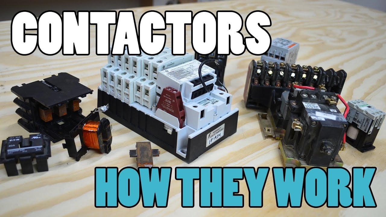
Was ist ein Schütz und wie funktioniert es? Von Electrician U wird visuell ein Überblick über den Betrieb von Kontaktoren und Hochspannungs-Schaltanlagen gegeben. Es ersetzt weder die schriftlichen Designanforderungen noch die spezifische Validierung des Produkts.
Sieh dir das Lernvideo auf YouTube an.
Häufig gestellte Fragen
What is the first rule for battery string contactor?
Definieren Sie die Schaltungsgrenze und alle Quellen, die sie mit Strom versorgen können, und verifizieren Sie dann die genaue Funktion der Geräte anhand der gemessenen Spannung- und Stromkurven.
Kann die Hilfserfassung beweisen, dass die Hauptkontakte geöffnet sind?
Nein. Korrelieren Sie den Hilfszustand mit der Busspannung, dem Strangstrom, dem Spulenstrom, der Zeitsteuerung und allen möglichen Rückkopplungswegen.
Sollte ein Kontaktor einen Strangschutzkontakt ersetzen?
Nein. Ein Kontaktor sorgt für eine gesteuerte Abschaltung, während ein Sicherungsschaltkörper einen Fehlerstromschutz bietet. Ihre Widerstand- und Entlüftungsfunktionen müssen aufeinander abgestimmt sein.
Welche Daten gehören in einer RFQ für BESS-Kontaktoren enthalten?
Umfassen Sie Spannungsbereich, Stromverläufe, Schaltzustände, Stromrichtung, Vorbelastung, Fehlerstrom, Schutz, Temperatur, Montage, Spulensteuerung, Rückkopplung und Lebensdauerziel.
Zuverlässige Referenzen
- OSHA 1910.147 – Kontrolle gefährlicher Energie
- OSHA 1910.333 – Praktiken bei elektrischen Arbeiten
- IEC 60947-4-1 — Relais und Motorstarter
- US-Energieministerium – Energiespeicherung
Verwenden Sie die von dem Projekt angenommenen Ausgaben und Anforderungen. Standards und Produktdaten können sich ändern, daher muss das zuständige Engineering-Team die endgültige Konstruktion bestätigen.





