Быстрый ответ: A battery string contactor connects one battery string to a shared BESS DC bus only after the controller proves compatible voltage, polarity, insulation, precharge, and communications. In parallel racks, it also isolates a faulty or serviced string without allowing the remaining strings to back-feed it. Safe operation depends on coordinated sequencing, current-sharing limits, string fuses, voltage sensing, feedback diagnostics, and controlled discharge.
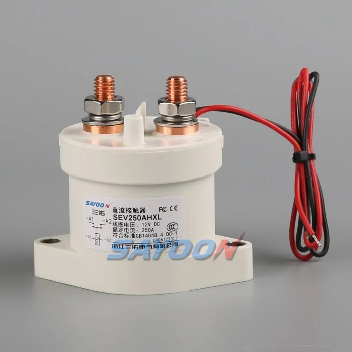
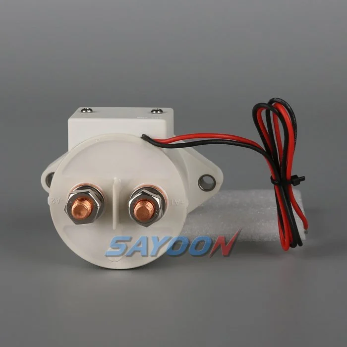
Настоящий путеводитель превращает эту тему в комплексный процесс проектирования, ввода в эксплуатацию и закупки оборудования BESS. В качестве визуального справочного материала использован реальный контактор Sayoon, при этом все характеристики, последовательности и решения по безопасности связаны с окончательной системой и текущей документацией производителя.
Карта инженерных решений
| Системное состояние | Ожидаемое состояние электричества | Концептуальный подход |
|---|---|---|
| String offline | Both mains open; bus may remain live | Prove isolation on both sides |
| Предварительный заряд | Precharge path active; mains open | Limit equalization current and verify voltage |
| Parallel online | Mains closed after voltage match | Monitor string current and sharing |
| String fault | Affected string opens; others remain controlled | Coordinate contactor, fuse, PCS, and discharge |
Ссылка на продукт и его область применения
Эт SEV250AHXL sealed high-voltage DC contactor является примером соответствующей реальной линейки продуктов. Проверьте Руководства высоковольтных токоприемников DC и Руководство по выбору контакторов постоянного тока для более широкого спектра рабочих процессов. Визуальный соответствие или номинальный ток не являются достаточными показателями для выбора модели для БЕС. Проверьте напряжение, текущий ток, рабочие характеристики, поляризацию, изоляцию, температуру, окружающую среду, срок службы, монтаж, конструкцию, драйвер и защиту вместе.
Why each string needs a controlled boundary
Parallel battery strings share a bus but do not remain identical. State of charge, temperature, internal resistance, cable resistance, and aging change each string voltage and current. A battery string contactor gives the BMS a controlled boundary for startup, fault containment, maintenance, and availability management. It is not a replacement for the string fuse and cannot correct cell imbalance.
The one-line diagram should show positive and negative mains, precharge branch, fuse, service disconnect, voltage and current sensors, insulation monitoring, auxiliary feedback, and the shared PCS connection. Mark every section that can remain energized when a single string is offline.
Match voltage before paralleling
Closing two strings with different open-circuit voltages can create a large equalization current limited mainly by impedance. Before closure, compare string voltage and bus voltage with sensors that have known accuracy and timing. Confirm polarity and communications. Use precharge or another approved matching method where required.
The acceptance window must include sensor error, contactor timing, capacitance, cable impedance, and the BMS strategy. A fixed delay does not prove voltage match. If the bus is outside the approved window, stop the sequence, identify the energizing source, and prevent repeated closure attempts.
Sequence the contactors and precharge path
A typical sequence verifies interlocks and insulation, closes the designated return path, activates precharge, watches bus voltage rise, closes the main path, then opens or de-energizes the precharge branch as designed. The exact order depends on the system. Document the expected voltage and feedback after every step.
On shutdown, reduce PCS current when possible, open the required mains, confirm current stops, and verify the isolated side. The shared bus can stay energized from other strings, so pack-side and bus-side measurements are both necessary.
Manage current sharing after closure
Once parallel, current does not divide perfectly. A lower-resistance or higher-voltage string can take more charge or discharge current. Monitor each string rather than relying only on total PCS current. Set warning and trip logic from validated battery and conductor limits, including sensor uncertainty and transient sharing.
Investigate persistent imbalance through state of charge, cell temperature, contact resistance, fuse and busbar joints, cable length, sensor calibration, and BMS estimates. Do not repeatedly open and close a string to force sharing unless the approved control strategy specifically supports that behavior.
Isolate faults without creating another fault
A string overcurrent, insulation fault, thermal event, communications loss, or contactor mismatch may require isolation. The controller must decide whether to reduce PCS power first, open the affected string, or shut the common bus. Opening under current must remain within the contactor duty and protection concept.
Other strings can feed the fault through the bus until the isolation and fuse sequence completes. Calculate prospective current and clearing energy. Preserve first-fault timing so the team can distinguish a battery fault from a welded contactor, failed driver, or incorrect current sensor.
Detect welded and stuck-open conditions
Compare contactor command, coil current, auxiliary feedback, string current, string voltage, and bus voltage. A closed auxiliary contact does not prove low-resistance main conduction. An open auxiliary contact does not prove that bus voltage has disappeared. Evaluate the complete circuit, including a parallel back-feed path.
After an open command, a persistent current is strong evidence of an unintended path. Similar voltage on both sides may be normal when the shared bus remains energized and the isolated string voltage is close, so use an approved diagnostic stimulus or discharge path rather than voltage equality alone.
Commission strings one at a time
Commission with production-intent racks, busbars, controllers, sensors, fuses, and PCS. Verify polarity, part numbers, drawings, terminal torque, coil supply, suppression, auxiliary logic, and sensor calibration before energizing. Bring one string online through the complete sequence while recording synchronized waveforms.
Repeat for each physical position, then test parallel connection, controlled removal of one string, communication loss, low control voltage, sensor faults, failed precharge, emergency stop, and restart restrictions. Use authorized procedures for hazardous energy and do not bypass interlocks to accelerate testing.
Document the operating envelope
Record the number of strings, battery voltage range, permissible voltage mismatch, charge and discharge currents, transient sharing, current at make and break, precharge capacitance and resistance, fault current, fuse clearing, temperature, enclosure, conductor resistance, switching cycles, coil driver, feedback, and service strategy.
The SEV250AHXL shown here is a product-family reference. Confirm the final part number and product-specific data for the real string duty. Keep calculations, raw waveforms, settings, deviations, and approvals with the as-built configuration.
Manage changes and periodic checks
Review the original evidence whenever cell chemistry, string count, PCS firmware, cable length, busbar, fuse, cooling, sensor calibration, contactor coil, driver suppression, or operating schedule changes. A physically interchangeable part can alter current sharing, pickup margin, release time, or fault coordination. Identify the affected assumptions and repeat the necessary tests.
During maintenance, inspect terminal joints, barriers, conductors, heat evidence, contamination, mounting, control wiring, and diagnostic history. Compare voltage drop and temperature only under comparable current and measurement conditions. After replacement work, exercise the complete approved sequence under representative load and confirm that one isolated string cannot be energized through the common bus or an auxiliary path. Record the reviewer and final disposition.
Контроль за безопасностью и доказательствами
Обращайте аккумулятор, общие конденсаторы, преобразователи, параллельные резервные устройства и испытательное оборудование к источникам опасной энергии до тех пор, пока уполномоченное лицо не выполнит процедуру изоляции участка и не проверит необходимую работоспособность с помощью измерительных приборов. Не подключайте обратные провода, не пытайтесь закручивать катушки, не пытайтесь устранить замыкания высокого напряжения и не открывайте устройства, не соответствующие их назначению. СИЭО может оставаться в работоспособном состоянии в том случае, если его подключение происходит в направлении, которое не очевидно на упрощенной схеме.
Определите пределы приемлемости на основе точных данных о продукте, утвержденных системных требований и репрезентативных испытаний. Запишите полный код заказа, изменения чертежа, опции для катушек, карту выводов, расположение проводников, места установки приборов, калибровку, температуру, версию программного обеспечения, исходные сигнатуры, критерии прохождения/отрицания, отклонения и рецензентов. Отдельно фиксируйте измерения и их интерпретацию. Если отсутствует доказательная база, запишите открытую операцию, а не введите стандартную величину.
Связанные инженерные руководства
Используйте Руководство по размерам предохранительных резисторов, Руководство по достоверности отзывов контактных лиц, Руководство по стойкости к короткому замыканию, и Руководство по координации утепления как дополнительные проверки. Эти страницы охватывают различные решения и должны применяться к той же утвержденной границе системы.
Обучающее видео
Что такое контактор и как он работает? Электрик U предоставляет визуальную информацию о работе контактора и переключении на высоковольтных токах. Это не заменяет письменных требований к проектированию или валидации по конкретным продуктам.
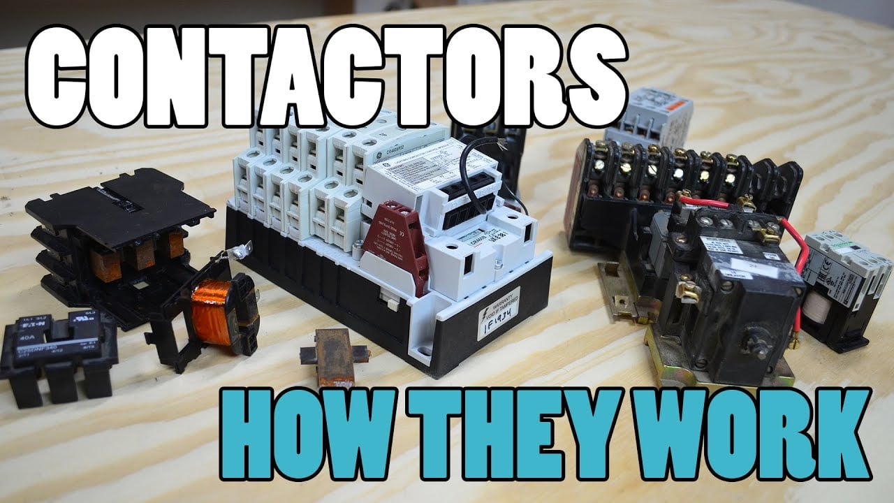
Посмотрите обучающее видео на YouTube.
Часто задаваемые вопросы
What is the first rule for battery string contactor?
Определите границы схемы и все источники питания, которые могут ее подавать питание, а затем проверьте точность работы устройств по измеренным параметрам напряжений и токов.
Может ли вспомогательная обратная связь подтвердить открытость основных контактов?
Нет. Сопоставьте вспомогательное состояние с напряжением на автобусе, током цепи, током катушки, временем и всеми возможными путями обратной подачей питания.
Необходимо ли заменить контактный элемент на шнуровой предохранитель?
Нет. Контактор обеспечивает контролируемое переключение, в то время как предохранитель обеспечивает защиту от перегрузки. Их характеристики в отношении стойкости и отключения должны быть согласованными.
Какие данные должны быть указаны в запросе на поставку оборудования BESS?
Включите диапазон напряжения, формы тока, режим работы «make and break», направление тока, предварительное наложение заряда, токовую утечку, защиту от перегрузок, температуру, монтаж, контроль катушки, обратную связь и целевой срок службы.
Авторитетные источники
- ОСХА 1910.147 — контроль опасной энергии
- ОСHA 1910.333 — практика электромонтажных работ
- IEC 60947-4-1 — контакторы и стартеры для электродвигателей
- Департамент энергетики США — энергохранение
Используйте принятые в рамках проекта издания и требования. Стандарты и данные о продукте могут измениться, поэтому ответственная инженерная команда должна подтвердить окончательный проект.





