Le 12 volt plastic DC contactor part no. 852-1251-210-50 is commonly identified as an intermittent-duty starter contactor rather than a continuous-duty battery disconnect. A safe replacement decision therefore cannot be based on “12 V” and “200 A” alone. Buyers should verify the grounded-coil arrangement, contact and coil terminals, mounting bracket, operating duty, temperature and environmental exposure, then confirm the candidate with drawings, samples and controlled application tests. Sayoon does not claim a drop-in replacement for this third-party part number; the purpose of this guide is to show the evidence an engineer should collect before approving any alternative.
Compatibility notice: Trombetta and 852-1251-210-50 are referenced for identification only. Sayoon is not affiliated with Trombetta. Any proposed alternative must be verified against the original specifications, installation and application requirements before use.
What the 852-1251-210-50 search results actually identify
The current Google results are dominated by distributors and replacement-parts sellers. Across those pages, the repeated description is a compact plastic 12 VDC starter contactor used for intermittent cranking or motor-starting service. A distributor listing for the original part identifies a grounded coil, two 1/4-20 copper contact studs, a 10-32 coil stud with a spade connection, a universal bracket, 200 A intermittent current and a 15% sustained duty statement with a 20-second maximum on-time. Those details are useful as a reference, but the purchasing team should still obtain the manufacturer drawing or an approved machine service document for the exact installed unit.
This distinction matters because search listings often compress several configurations into one product title. A visually similar plastic contactor may have an isolated coil instead of a grounded coil, a different bracket, different control terminals, or a continuous-duty contact system. Those differences can prevent operation or create an unsafe installation even when the nominal coil voltage matches.
| Verification field | Reference description seen for 852-1251-210-50 | What the buyer must confirm |
|---|---|---|
| Bobine | 12 VDC, grounded configuration | Actual control voltage range, polarity if applicable, grounding path and pull-in behavior |
| Principaux interlocuteurs | Normally open starter path; copper contact studs | Contact form, make/break requirement and DC utilization category |
| Current and duty | 200 A intermittent; short cranking duty | Peak current, crank duration, starts per hour, ambient temperature and recovery time |
| Terminaux | Two 1/4-20 power studs; small stud plus spade for the coil | Thread, lug stack, washer order, cable clearance and terminal torque from the approved drawing |
| Mounting | Universal metal bracket | Hole spacing, orientation, bracket stiffness, grounding and vibration environment |
Reference identification: the publicly available Waytek listing for 852-1251-210-50. Treat distributor data as a starting point and reconcile it with the exact manufacturer drawing and equipment documentation.
Why 200 A does not define an equivalent contactor
A current number is incomplete without duty and test conditions. Starter contactors usually carry high current for a short period and then remain open long enough to cool. A continuous-duty contactor must manage coil heating and contact temperature for a much longer energized interval. Substituting an intermittent device into a circuit that stays closed can overheat the coil or terminals. Substituting a continuous-duty product into a starter circuit can also fail if its peak making capability, voltage drop, mechanical fit or control arrangement is wrong.
Record the measured cold-crank current and the highest credible current during a stalled or difficult start. Then record the normal on-time, maximum on-time, number of starts per hour, lowest battery voltage during cranking, highest enclosure temperature and cable size. That operating profile is more useful to a supplier than the single phrase “200 amp solenoid.”
Check the grounded coil before comparing candidates
A grounded-coil contactor uses its mounting or case connection as part of the coil circuit. An isolated-coil version brings both coil connections to dedicated terminals. These arrangements are not automatically interchangeable. A machine harness designed for one small trigger wire may not energize an isolated coil without a return lead. Conversely, a grounded-coil unit may create an unintended return path in equipment designed to isolate the control circuit.
Before removing the old unit, label the cables and photograph the installation only after the equipment has been placed in an approved electrically safe condition. Trace the control return using the machine schematic rather than assuming the bracket is merely mechanical. OSHA 1910.333 requires exposed live parts to be de-energized before work unless a specific exception applies. The site’s qualified-person procedure and the equipment manufacturer’s instructions control the actual task.
Verify mounting, terminals and cable geometry
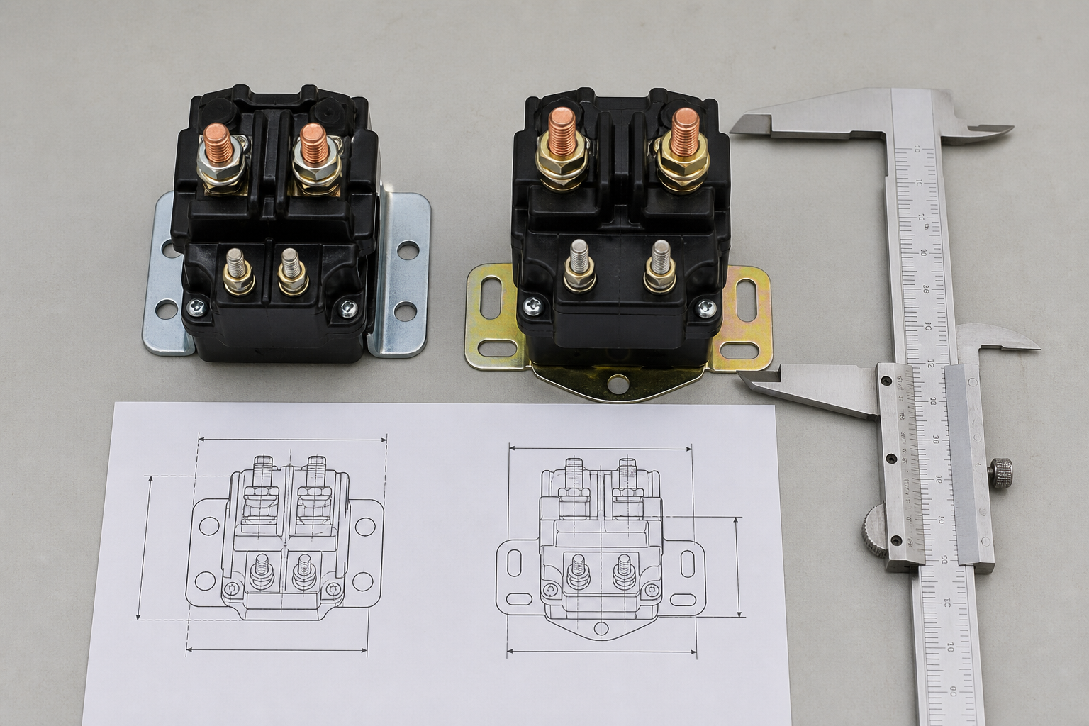
Mechanical compatibility is a functional requirement. A replacement that fits the bolt holes can still put a power stud too close to a cover, force the cable lug to twist, or leave insufficient creepage and clearance around conductive hardware. Compare overall height, body width, mounting-hole centers, bracket thickness, stud locations, thread sizes and the space required for the complete lug-and-washer stack.
Do not enlarge cable lugs or improvise washers simply to make a different stud fit. The joint must be assembled to the approved terminal hardware and torque. Cable stiffness also matters: a short heavy cable can transfer vibration and bending force into the plastic housing. Verify that the installed cable route does not preload the studs and that boots or barriers can be restored.
Separate starter duty from motor switching duty
Some seller descriptions mention small-engine starting and electric motors in the same paragraph. Those uses are not automatically equivalent. A starter circuit normally closes before a high-current cranking event and opens after the engine starts. A traction or pump motor contactor may close and open current repeatedly, may experience regenerative voltage, and may need documented DC breaking capability. Ask whether the contactor must only make current, must interrupt running current, or must interrupt a stalled motor. Also record the system voltage at opening, because DC arc extinction becomes more demanding as voltage increases.
If the application is a sustained motor, battery disconnect or industrial control function, use a product selected for that documented duty rather than treating a lawn-and-garden starter contactor as a universal 12 V switch.
How to evaluate a Sayoon engineering candidate
Le Sayoon SDC15-200A starter DC contactor can be discussed as an engineering candidate when the application is a low-voltage, high-current starter path. It is not presented as a drop-in replacement for 852-1251-210-50. Published Sayoon information describes different terminal sizes, contact material and enclosure characteristics, so a drawing-to-drawing comparison is mandatory.
Start from the broader Gamme de contacteurs CC de la série SDC and send the supplier the original drawing, wiring diagram, duty profile and environmental requirements. A useful response should identify every mismatch rather than merely repeat the desired voltage and current.
| Review stage | Evidences | Stop condition |
|---|---|---|
| Document review | Original and candidate drawings, wiring diagram, ratings and materials | Any unexplained electrical, duty, terminal or dimensional mismatch |
| Incoming sample | Dimensions, terminal identity, coil resistance and workmanship | Sample differs from approved drawing or cannot be installed without modification |
| Controlled bench test | Pull-in/release behavior, voltage drop and temperature under an approved test plan | Unstable operation, excessive temperature or abnormal voltage drop |
| Machine validation | Worst-case starting cycles, vibration, enclosure clearance and fault response | Any behavior outside the equipment maker’s acceptance criteria |
Build a controlled validation plan
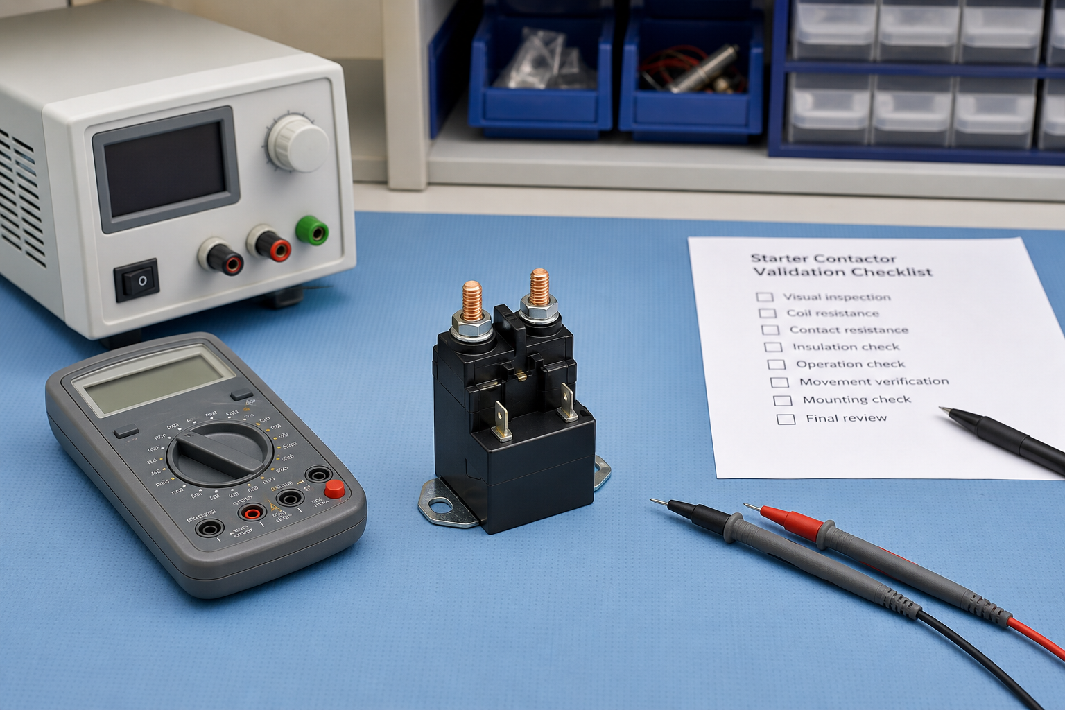
After the document review, inspect the sample before applying power. Confirm the terminal identification, mounting integrity and coil resistance against the supplier’s approved data. A controlled functional test should use current limiting and instrumentation appropriate to the circuit. Record pull-in at the lowest expected control voltage, release behavior, closed-contact voltage drop, temperature rise over the intended duty cycle and repeatability across multiple operations.
Application testing should reproduce the worst credible start rather than only a no-load click test. Confirm that cables and boots fit without stress, the bracket stays secure, the control circuit does not backfeed, and the contactor releases after the command ends. Follow the facility’s energy-control program; OSHA 1910.147 provides requirements for controlling hazardous energy during servicing.
Information to include in an RFQ
A good request for quotation lets the manufacturer evaluate the application rather than guess. Include the original part number only as an identification reference and attach:
- original drawing, photographs and mounting-hole dimensions;
- 12 V control range, minimum voltage during crank and grounded/isolated coil requirement;
- normal, peak and fault current with maximum on-time and starts per hour;
- power-stud and coil-terminal requirements, cable size and lug stack;
- ambient temperature, vibration, moisture, dust and chemical exposure;
- required documentation, sample quantity and acceptance tests.
For a broader process, see the guide to preparing a DC contactor sample request and RFQ record. Teams replacing an unknown unit should also review how to use a contactor nameplate in a replacement review et how to test a DC contactor without guessing at the fault.
Vidéo : principe de fonctionnement d'un contacteur
This neutral educational video explains the basic coil, armature and contact operation. It supports the terminology used above but does not replace the original machine documentation or a qualified electrical review.
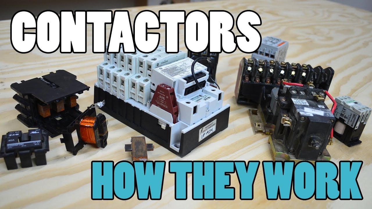
À regarder sur YouTube : Qu'est-ce qu'un contacteur et comment ça marche ? — Electrician U
Foire aux questions
Is 852-1251-210-50 a continuous-duty contactor?
The repeated public description is an intermittent starter contactor with a short-duty limitation. Do not use it as a continuous-duty device unless the exact manufacturer documentation explicitly approves that operating profile.
Can any 12 V 200 A solenoid replace it?
No. Coil grounding, contact duty, terminal threads, mounting, pull-in voltage, environmental protection and cable geometry must also match the application.
Is the Sayoon SDC15-200A a direct replacement?
No direct-replacement claim is made. It is an engineering candidate only when its drawing, ratings and application test results meet the project requirements.
What should be measured before ordering a sample?
Measure the mounting pattern and available envelope, identify every terminal, record current and duty, and capture the lowest control voltage during starting.
Who should approve the replacement?
The equipment owner’s qualified engineering or maintenance authority should approve it using the machine documentation, supplier data and controlled test results.





