Contactor utilization categories describe standardized load and switching duties; they do not merely rename the current rating. Categories distinguish resistive loads, motors, plugging or inching, and other operating conditions because make and break stress differs. Confirm the applicable standard edition and exact category in the manufacturer’s data. Do not assume an AC category proves DC performance, or that the same ampere value transfers between categories. This article explains a controlled review method; it does not replace the selected contactor’s data sheet, applicable standards, or a qualified electrical safety assessment.
Key review points
| Review item | Evidence to collect | Pourquoi c'est important |
|---|---|---|
| Current type | Separate AC and DC category families | Arc behavior and test duties differ |
| Load behavior | Identify resistive, motor, capacitive, or inductive characteristics | Steady current alone is insufficient |
| Operation | State start, stop, inching, plugging, or isolation | Switching severity changes by sequence |
| Voltage | Match the rated operational voltage | Category ratings are voltage-specific |
| Life target | Define operations and maintenance strategy | Electrical endurance depends on duty |
What categories add to the rating plate
A utilization category connects a contactor to a defined application and test duty. It helps users distinguish easy carrying service from repeated motor starting or interruption of an inductive load. The category, operational voltage, operational current, and test conditions must be read together.
Apply this point to the actual operating envelope rather than a nominal bench condition. Record both the commanded state and the measured response, note any controller or protection action, and retain evidence that another reviewer can reproduce. If the product documentation does not state the needed boundary, treat the selection as unresolved and ask the manufacturer for written confirmation.
AC and DC categories are not interchangeable
AC circuits pass through natural current zero, while DC interruption must force the arc to extinguish by other means. Motor time constants, resistive heating, capacitor inrush, and regenerative current further change stress. An AC-rated contactor should not be moved into a DC path without explicit DC evidence.
Apply this point to the actual operating envelope rather than a nominal bench condition. Record both the commanded state and the measured response, note any controller or protection action, and retain evidence that another reviewer can reproduce. If the product documentation does not state the needed boundary, treat the selection as unresolved and ask the manufacturer for written confirmation.
How to translate an OEM application
Describe the actual load waveform first, then identify the closest applicable category with the manufacturer or responsible engineer. For traction and battery systems, include precharge, acceleration, regeneration, emergency isolation, stalled motor, and fault coordination rather than forcing every event into one normal-use label.
Apply this point to the actual operating envelope rather than a nominal bench condition. Record both the commanded state and the measured response, note any controller or protection action, and retain evidence that another reviewer can reproduce. If the product documentation does not state the needed boundary, treat the selection as unresolved and ask the manufacturer for written confirmation.

How to turn the topic into an engineering decision
Begin with the approved schematic, product drawing, and operating sequence. Record the minimum and maximum control voltage, main-circuit voltage, normal and abnormal current, switching frequency, ambient range, enclosure, mounting, conductor interfaces, and protective devices. A short part number or headline ampere value cannot represent all of those conditions.
Next, separate observation from interpretation. An observed delay, temperature, voltage drop, or resistance is data. The proposed cause is a hypothesis that needs a controlled check. Change one variable at a time where practical, retain the instrument and setup details, and compare the result with the exact manufacturer criteria. This prevents a wiring fault, weak control supply, loose terminal, or unsuitable load from being misdiagnosed as a defective contactor.
Finally, review the result at system level. A change that improves one behavior can worsen another: stronger surge suppression may delay release; a sealed chamber may change thermal behavior; a lower-power coil driver may reduce pickup margin; and a contactor with ample carry current may still lack the required breaking evidence. Approval belongs to the complete combination of device, driver, load, protection, installation, and operating logic.
Verification workflow before approval
- Define the state. Mark which sources are isolated, where stored energy remains, and whether the test concerns the coil, auxiliary contacts, or main current path.
- Confirm identity. Photograph the nameplate and terminals, record the full part number and revision, and obtain the matching drawing and data sheet.
- Measure at the device. Place voltage or sensing leads at the relevant contactor terminals so cable and controller effects remain visible.
- Exercise the real sequence. Include precharge, interlocks, delays, normal stop, abnormal stop, and restart conditions that the machine actually uses.
- Repeat and stabilize. Record cold and warm results and enough cycles to reveal variation. Do not accept one favorable operation.
- Compare with written limits. Use product-specific evidence and the current approved project requirements. If a limit is absent, request it rather than inventing one.
- Release with traceability. Retain the setup, instruments, conditions, results, reviewer, and final disposition with the drawing revision.
Limite de sécurité Treat the power circuit as hazardous until an authorized person has isolated every energy source, applied the site lockout procedure, verified absence of voltage with a suitable instrument, and addressed stored energy. The OSHA control-of-hazardous-energy rule et Exigences de l'OSHA en matière de pratiques de travail sur les installations électriques provide the general safety framework; the equipment manufacturer and project rules govern the actual procedure.
What the handover record should contain
A useful handover record lets a buyer, panel builder, test engineer, and service technician reach the same conclusion without relying on memory. Include the full contactor and coil ordering codes; approved drawing revision; terminal function and cable destination; controller type and software state; supply tolerance; load waveform; switching sequence; ambient and enclosure conditions; instrument model and calibration status; photographs of the setup; raw readings or traces; pass/fail criteria; deviations; and reviewer approval. Record units beside every number and distinguish measured values from catalogue values. If a sample differs from the production-intent assembly, list every difference. This record is especially important when a contactor is being substituted, because an apparently minor change in internal suppression, terminal orientation, arc-control direction, or hold-current strategy can alter system behavior even when nominal voltage and current look similar.
Decision traps to avoid
Do not approve the device because a single bench demonstration looks successful. A room-temperature test with short leads, no enclosure, no vibration, and a resistive substitute load may conceal the exact weakness that appears in service. Do not combine the most favorable values from several catalogue tables unless the manufacturer confirms they apply simultaneously. Avoid treating an auxiliary contact as proof that the main contacts carried or interrupted the intended current; feedback contacts report mechanism position only within their own documented behavior. Do not adjust controller timing to hide slow or inconsistent contactor operation before the electrical and mechanical cause is understood. Finally, do not copy acceptance limits from a different model, coil option, voltage class, or test method. When evidence is incomplete, the correct status is pending engineering review, not provisional approval. These controls keep contactor utilization categories decisions traceable and prevent a convenient assumption from becoming a production requirement.
Product and RFQ connection
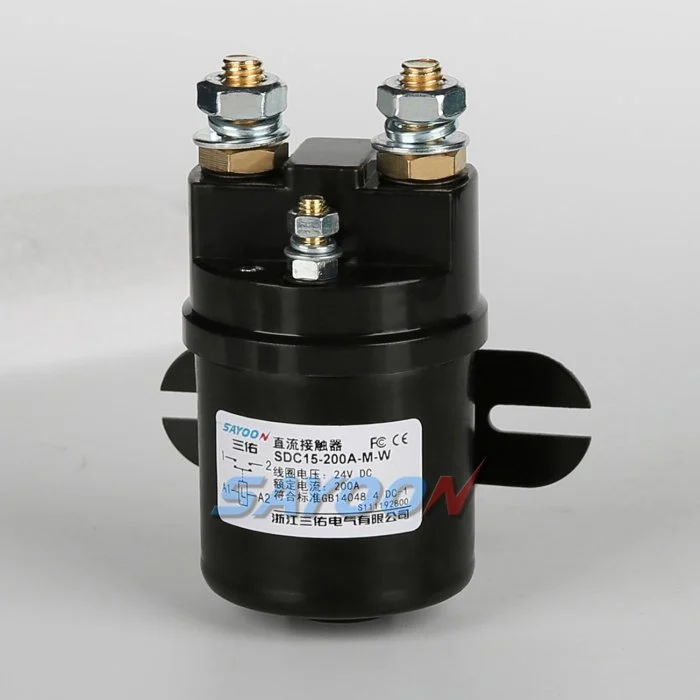
Sayoon product families provide different current classes, contact arrangements, enclosure styles, and coil options. The linked Contacteur DC de démarreur SDC15-200A is a relevant product example, not automatic approval for every condition described here. Send the actual circuit, duty, environment, mechanical envelope, cable interfaces, and required test evidence with the enquiry. The engineering review should confirm the complete ordering code and drawing before samples or production parts are released.
For a broader comparison process, use the DC contactor selection guide, the safe contactor test workflow, and the coil-voltage guide hub. These pages address adjacent decisions without replacing the single question answered in this article.
Educational video
Introduction to Utilisation Categories by NHP Electrical Engineering Products provides a visual introduction related to this review. The written procedure above remains the controlling guidance.
Foire aux questions
Is AC-3 the same as a motor horsepower rating?
No. It is a standardized duty concept that must be used with the product’s voltage and current data.
Can an AC-1 rating be used for a DC resistor load?
Not automatically. Use a stated DC rating or category for the required voltage and duty.
Do utilization categories cover fault interruption?
They define operational duties; fault protection and short-circuit coordination require separate evidence.
What if the load does not fit one category?
Provide waveforms and operating sequences for a product-specific engineering review.
Where are category definitions maintained?
They are defined in applicable switchgear and controlgear standards; use the current approved edition and manufacturer declarations.
Final checklist
Before release, confirm the exact part number, drawing revision, coil and main-terminal functions, load waveform, protection, environment, installation, measurement method, acceptance criteria, and reviewer. Check that the test did not bypass an interlock or create a condition outside the device rating. If the candidate is a replacement, compare interfaces and behavior field by field; similarity of size or nominal current is not proof of equivalence.
IEC 60947-4-1 is a relevant standards reference for electromechanical contactors and motor-starters. Always use the edition adopted by the project and obtain the full normative requirements through the responsible standards process.





