A 1500V DC contactor must have documented suitability for the full operating voltage, assigned DC switching events and insulation conditions of the equipment. For photovoltaic and storage systems, establish the maximum source voltage, possible backfeed, continuous current and fault coordination before selecting a device. A 1500V label is not a blanket approval for every circuit at that voltage. Keep the coil supply separate, and do not assume two lower-voltage devices in series create an equivalent qualified 1500V assembly.
This guide is for builders and purchasers reviewing a PV-connected converter, battery interface or industrial DC assembly. It focuses on the source conditions and evidence needed to approve the contactor, rather than providing a universal clearance, current margin or live testing procedure.
Define the maximum source voltage first
For a photovoltaic source, use the approved array design and module data to determine the maximum string voltage under the applicable temperature and installation assumptions. Normal running voltage and open-circuit voltage are different values. A warm operating measurement cannot establish the maximum voltage under all permitted conditions.
For a battery, specify its full-charge boundary, charging limits and permitted operating range. For a converter link, include the supported bus range and energy-recovery conditions. Where sources connect through converters, identify which nodes are energized in each state and what voltage the contactor actually experiences.
The U.S. Department of Energy’s PV system design overview introduces the wider system and power-conversion context. It does not qualify a contactor or replace the array’s electrical calculations. Retain the equipment designer’s maximum-voltage result and assumptions.
Assign the contactor’s role in the PV or storage circuit
State whether the device routinely connects a source, opens a defined load current, or changes state only after a converter reduces current. The role determines the making and breaking evidence needed. A source-side device can face different conditions from a contactor downstream of a controlled converter.
Do not automatically describe the contactor as an isolator for maintenance. An equipment switching function and a verified safe-work isolation arrangement have different requirements. Identify the dedicated isolation points, stored energy and alternate sources in the equipment documentation.
Document how the controller confirms readiness to open or close. A requested converter stop is not proof of current reduction. If the intended sequence depends on a signal that can fail, review the resulting duty and required protective response with the equipment designer.
Collect separate voltage and duty evidence
| Review field | Equipment information | Evidence to request |
|---|---|---|
| Maximum source voltage | Approved PV string or battery upper boundary | Operating range covering the real maximum |
| Opening role | Loaded interruption or post-reduction switching | Applicable DC breaking qualification |
| Source direction | Generation, charging, backfeed and fault paths | Permitted interruption directions |
| Insulation installation | Environment, altitude, barriers and control separation | Model-specific limits and complete equipment assessment |
| Startup | Converter capacitor state and precharge sequence | Making-duty evidence |
| Fault coordination | Every available source and protective device | Supported carry, withstand or interrupt role during clearing |
The review table deliberately leaves numeric limits to the approved product and equipment documents. There is no universal rule that a particular contactor body size, coil type or terminal spacing makes it suitable for a 1500V installation.
Understand the scope of the contactor standard
The official IEC 60947-4-1 publication record includes relevant contactor equipment for circuits up to 1500V DC within its stated scope. That scope does not mean every contactor referring to the standard has a 1500V rating. Verify the product’s exact classification and supported duty.
Ask for the applicable edition, rating conditions and evidence associated with the ordered model. Keep operating voltage, insulation-related values and switching limits in separate fields. Certification or test claims should identify their scope and ordering codes rather than appearing as unsupported general badges.
The finished equipment may have additional requirements for source disconnection, insulation, enclosure, installation and servicing. The equipment builder remains responsible for the complete design. A component document can support that review but does not settle all system-level obligations.
Trace backfeed and interruption direction
A DC network may have PV generation, batteries, parallel converters or multiple storage strings. Draw current paths during generation, charging, discharge and abnormal conditions. Backfeed can change the direction and source sustaining current through the contactor.
Confirm whether the device’s arc-control arrangement supports the opening directions actually assigned to it. Closed-contact conduction in either direction does not prove bidirectional interruption. Specify what happens if a source remains active when another source is stopped or disconnected.
Assess voltage across the open device in each state. Do not divide the total voltage by the number of contactors unless the arrangement has justified voltage sharing and suitable qualification. A faulted or unsynchronized device can change the voltage distribution and invalidate that assumption.
Keep converter charging separate from source isolation
A converter DC link may need a controlled charging sequence before the main path closes. Record capacitance, initial voltage difference, the precharge arrangement and the completion criterion. A source contactor with adequate carrying capability can still face an unsupported capacitor-charging event.
Specify how the sequence responds to failed charging, partial charge and a restart after lost control power. Determine whether retries are permitted and how the system avoids repeated closure into an unresolved condition. Use the actual converter design and switching evidence rather than a generic time delay.
Precharge does not create a maintenance isolation function. The source may remain energized and capacitors may retain charge after normal switching. Keep those states visible in the circuit documentation and service procedure instead of treating every stopped state as de-energized.
Review insulation, enclosure and environment
Check terminal-to-terminal, power-to-control and power-to-mounting insulation in the installed assembly. Request the permitted mounting orientation, conductor arrangement, barriers and environmental limits. External creepage and clearance must be assessed for the actual equipment conditions and applicable requirements.
Outdoor or containerized installations can introduce condensation, contamination and temperature changes. The sealing of a contactor does not automatically protect exposed terminal joints or the complete enclosure. Review the enclosure and installation together rather than assigning system protection from one component’s appearance.
Altitude and surrounding air conditions may affect the insulation and thermal assessment. Obtain documented limits and any required qualification. Do not invent a universal derating percentage or distance from the voltage number alone.
Coordinate fault protection and thermal duty
Identify the prospective fault from every source that can feed the contactor location. Assign a fuse, breaker or other protective device and establish what the contactor must carry, withstand or interrupt while protection operates. A routine connector is not automatically the device that clears a source-fed fault.
For sustained current, use the actual operating profile, enclosure temperature and installed conductors. Review terminal heating and mechanical loading as well as the internal path. Document the supported connection hardware and fastening instructions for the ordered model.
For servicing covered by the rule, OSHA 1910.333 addresses de-energization and verification. Source isolation and stored energy require the appropriate procedure. An opening command or feedback signal cannot replace verification of the actual electrical condition.
Ask for a supported model rather than a visual match
Send voltage calculations, circuit states, current profile, interruption events, source directions, control supply, environment and protection to the supplier. Request an exact ordering code with its supported limits. If the available range cannot meet the duty, resolve that boundary before purchasing.
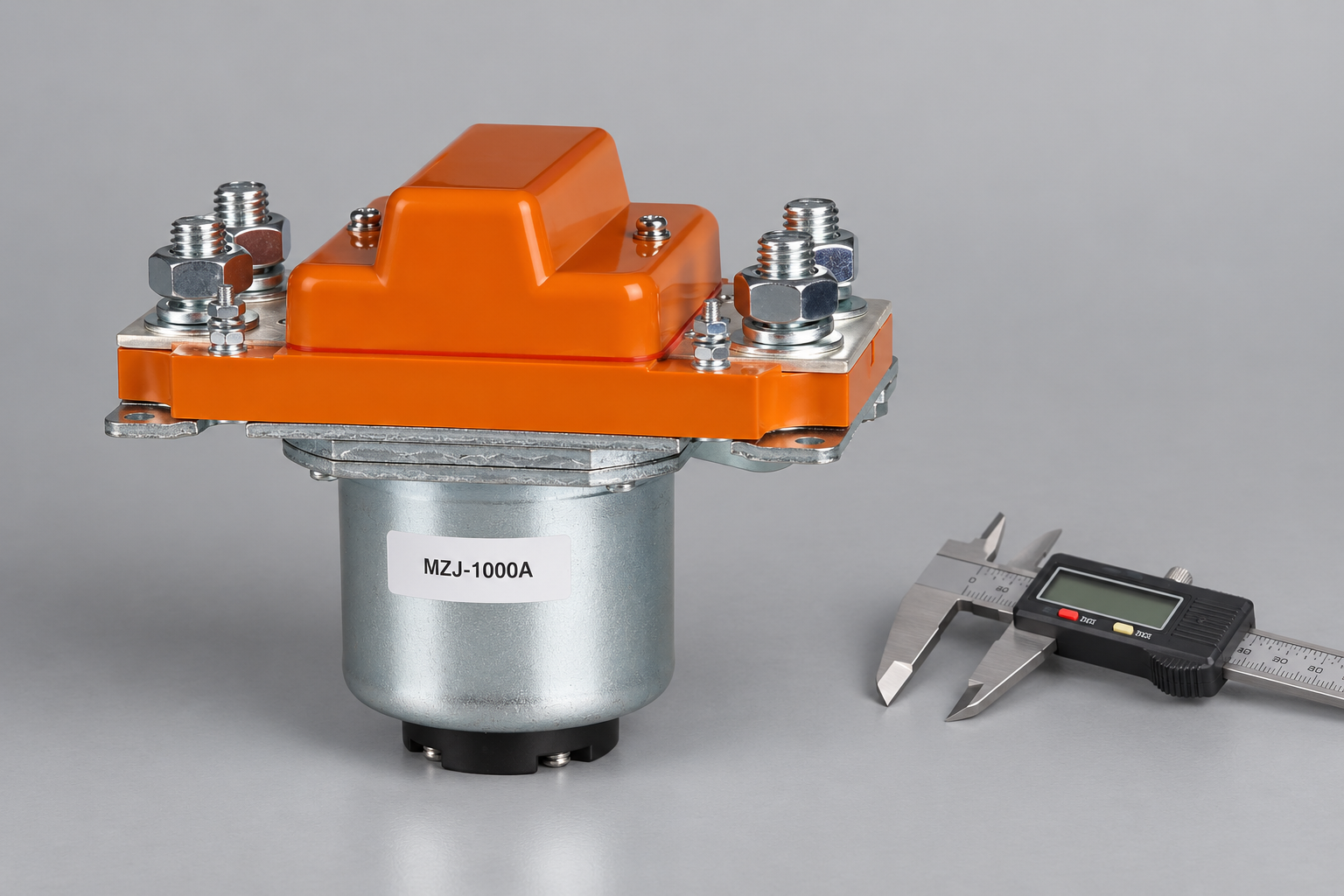
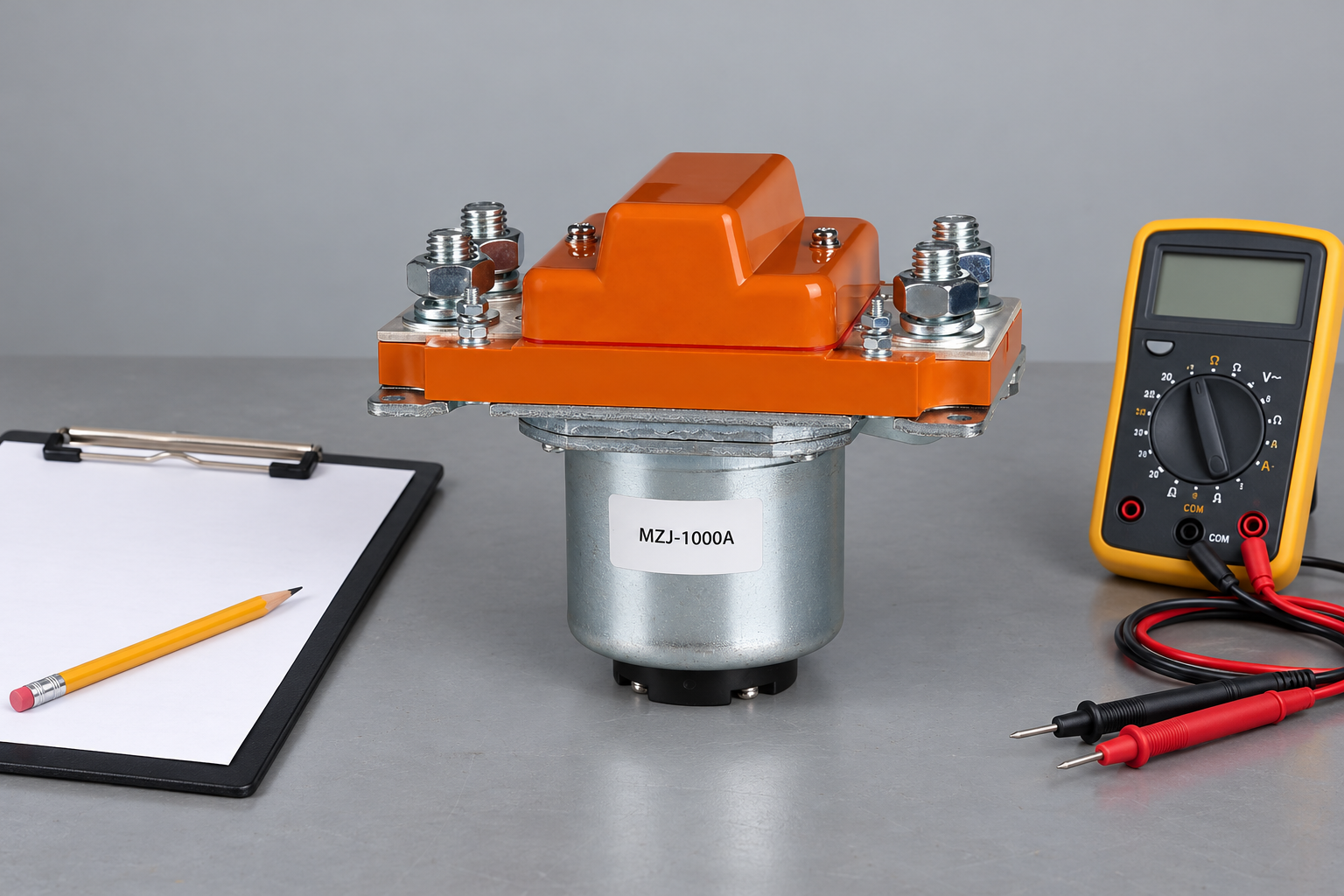
Review the MZJ-1000A Normally Open DC Contactor product page for an external construction reference. This conventional construction example is not a qualified candidate for the article’s stated duty; obtain an appropriately rated variant and product-specific evidence from Sayoon. This image is a sealed-contactor construction example; it makes no claim that the illustrated model supports 1500V. Use the OEM specification checklist to organize the evidence. For focused supporting checks, review solar battery contactor selection, e parallel battery-string switching. Keep the documented qualification and installed validation with the purchasing record, including any application limits that a replacement must preserve.
Keep source assumptions traceable through procurement
Attach the approved maximum-voltage calculation to the supplier request. Identify its module or battery data, source configuration, applicable temperature assumptions and revision. If a project later adds modules, changes a charger limit or connects another source, revisit the contactor selection before treating the existing approval as transferable.
Ask the supplier to respond to the stated circuit arrangement rather than a broad application name such as solar or energy storage. Two projects with the same voltage headline can assign very different opening duties and source directions. A documented boundary makes it possible to assess a proposed change without starting from an unsupported catalog assumption.
Watch the basic contactor operating principle
Electrician U explains the electromagnetic contactor mechanism in this educational video. It supports the operating principle only; it does not demonstrate the selected model’s DC ratings, qualify this application or replace product documentation.

Watch the Electrician U contactor explanation on YouTube.
Domande frequenti
Does IEC 60947-4-1 scope make every contactor suitable for 1500V DC?
No. The standard scope is not a product rating. Verify the exact model, ordering code, classification and supported switching duty.
Can two lower-voltage contactors replace a 1500V-rated device?
Only with a justified and qualified assembly design. Do not assume equal voltage sharing or equivalent interruption capability.
Should PV operating voltage alone determine the contactor voltage rating?
No. Use the approved maximum source-voltage calculation and relevant circuit states, including open-circuit and temperature conditions.
Does opening the source contactor remove all stored energy?
No. Converter capacitors and other sources can remain energized. Follow the equipment isolation and verification procedure.





