A contactor auxiliary contact rating must match the voltage, current, load type, switching frequency, fault protection, and required reliability of the control circuit. Do not choose it from the main contactor’s ampere rating. A small auxiliary contact that reliably reports a PLC input may be unsuitable for interrupting a DC contactor coil, while a contact rated for an inductive control duty may still have a minimum current below which signal reliability is not guaranteed. Select the exact NO or NC contact by its utilization category and manufacturer table, then validate the complete circuit and fault response.
Separate signal duty from switching duty
Auxiliary contacts commonly provide status, seal-in logic, electrical interlocking, alarms or controller feedback. Each function creates a different electrical duty. A PLC input may draw only milliamperes; a relay or contactor coil is an inductive load whose interruption produces a transient. A lamp can have a cold-filament surge. Do not use a single generic “10 A” number across those cases. Read the contact’s rated operational current at the actual control voltage and utilization category.
For IEC-style ratings, DC-13 is associated with switching DC electromagnets. Schneider Electric’s technical catalogue describes DC-13 for electromagnetic loads. This explains the category, but it is not a rating for a Sayoon auxiliary contact. Use the exact Sayoon drawing and data for the ordered option. For low-level signals, also request minimum permissible voltage/current or contact reliability data; a maximum rating does not guarantee dependable dry-circuit performance.
Collect the load information before selecting
Record whether the auxiliary contact makes, breaks or only carries the load; normal and fault voltage; steady and transient current; inductance or time constant; suppression; expected operations per hour and lifetime; ambient conditions; conductor size; and protective device. For controller feedback, include input leakage, diagnostic pulses and wetting-current requirements. For an interlock, document whether a normally closed contact must positively prevent the opposing coil from energizing and what happens if the contact welds, opens or is miswired.
| Application | Key rating evidence | Main risk | Verification |
|---|---|---|---|
| PLC status input | Minimum and maximum signal current/voltage, contact reliability | Oxide or leakage causes false state | Measure input thresholds over life and environment |
| Contactor coil switching | DC inductive category at actual voltage/current | Arc, erosion or welding on opening | Check category, suppression and endurance |
| Electrical interlock | NC contact duty and required fault behavior | Both coils commanded after contact failure | Fault test plus mechanical interlock where required |
| Indicator lamp | Inrush and steady lamp current | Cold-filament surge | Use lamp-specific manufacturer rating |
| Safety-related feedback | Defined contact architecture and safety data | Assuming ordinary auxiliary equals mirror contact | Validate complete safety function |
Check NO/NC state and mechanical relationship
“Normally” refers to the device’s defined de-energized condition. Confirm whether the selected block supplies NO, NC or changeover poles and map every terminal from the current drawing. Do not infer state from physical position or another model. For feedback, determine whether the auxiliary is mechanically linked in a way appropriate to the diagnostic claim. An ordinary auxiliary transition does not necessarily prove all main contacts opened or that hazardous DC voltage is absent.
Siemens documents auxiliary-circuit uses including signaling and interlocking and publishes model-specific low-level reliability boundaries. This reinforces two selection lessons: verify the intended function and use the exact device data. It does not transfer Siemens ratings to Sayoon products.
Account for suppression, protection, and endurance
When an auxiliary contact interrupts a coil, suppression changes arc stress and release time. A diode can reduce transient voltage but prolong DC coil current decay. A higher-voltage clamp may release faster while imposing more voltage on the switching device. Confirm compatibility with coil polarity, the contact rating and required timing. Do not add suppression when the coil already includes electronics without manufacturer approval.
Short-circuit protection does not turn an undersized auxiliary contact into an acceptable switch. Select a fuse or protective device within the manufacturer’s coordination guidance and conductor rating. Estimate electrical operations from real switching frequency and expected service life, not mechanical endurance alone. Environmental contamination, vibration and infrequent low-level operation can matter. Preserve replacement part numbers so maintenance does not substitute a block with a different contact material or category.
Commission the complete control function
- Verify the exact contactor, auxiliary block, terminal map and normal state.
- Identify load type, voltage, make/break current, suppression and switching frequency.
- Compare the manufacturer’s rating at the exact voltage and utilization category.
- Check minimum signal duty when feeding electronics.
- Confirm conductor, terminal and short-circuit protection requirements.
- Measure voltage and current during operation and capture the inductive transient if relevant.
- Exercise open-wire, welded-contact, stuck-coil and power-restoration scenarios defined by the design.
- Record state timing, contact resistance trend, drawings and replacement identity.
For an interlocking application, follow our DC contactor interlock guide. For controller status, the PLCコイル制御ガイド explains why command and feedback are separate. Use the selection guide to keep main-contact, coil and auxiliary requirements distinct.
Connect the choice to an actual product order
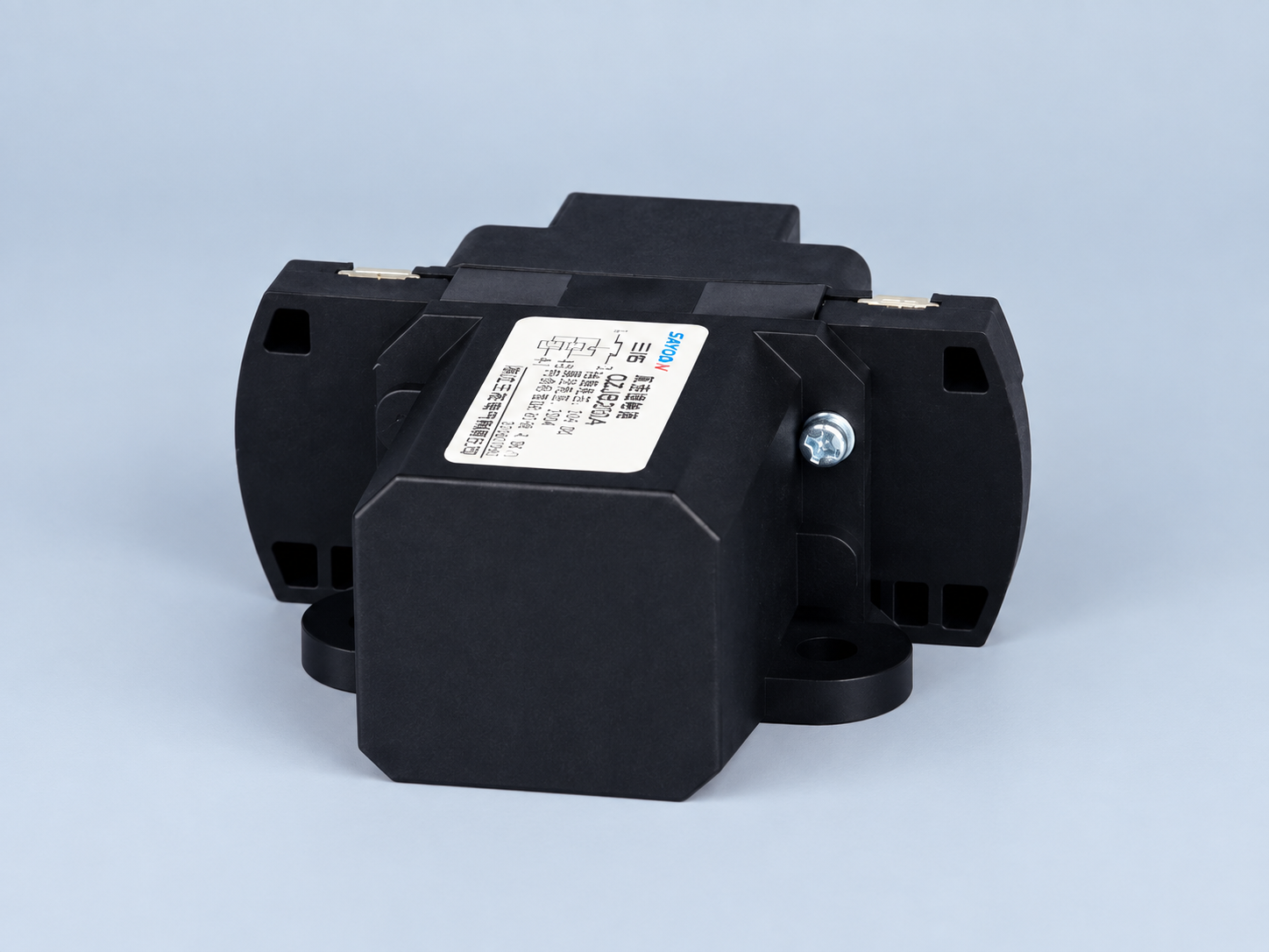
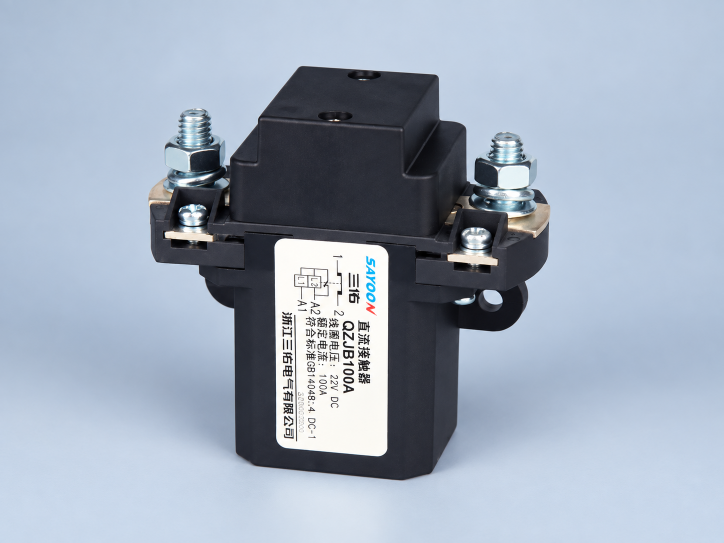
その Sayoon QZJB200A product page is the featured product reference. A normally closed main-contact description does not automatically specify an auxiliary block. Send the required NO/NC count, signal or load details, control voltage, utilization duty, switching rate, life expectation, protection, environment and drawing requirements with the RFQ. Ask for explicit confirmation of terminal mapping and auxiliary ratings for the exact order code.
Avoid recurring selection mistakes
Do not use thermal carry current as make-and-break duty, apply an AC rating to a DC inductive circuit, assume a power contact will reliably switch microamps, count an ordinary auxiliary as a safety mirror contact, or treat a compatible mounting shape as electrical approval. Each shortcut removes a condition that manufacturers specify separately.
Contact bounce and controller filtering matter. A PLC may see several transitions during one operation, while another filter hides a slow change. Define timing from measured behavior. For seal-in logic, verify loss and restoration of power. For alarms, decide whether an open wire appears normal, alarm or fault. The electrical rating alone cannot answer those system questions.
Control replacements and maintenance
Record block model, position, terminal numbers, conductor range and permitted number of blocks. Mark installed NO and NC poles. During maintenance, verify de-energized continuity only after isolation, then perform an approved functional test. Low resistance at test current does not prove future inductive breaking capability.
If contacts fail, investigate load duty, suppression, frequency, contamination, loose terminals and fault current before installing a larger device. A relay interface separates low-level feedback from coil switching but adds its own coil, contacts, suppression and failure modes. Select the whole chain. For safety-related systems, use components and architecture supported by the applicable validation plan.
最終デザインレビューと証拠パッケージ
リリース前に、元の設計者以外の人物が、現場の配線と承認された図面および正確な製品ドキュメントを比較してください。端子識別、導線の配線、トルク証拠、保護、コイル供給、抑制、接触状態、およびコントローラー設定を確認してください。すべての記載された許容限界にトレーサビリティのある情報源があること、およびイラスト的な例が非公式な製品評価に利用されていないことを確認してください。写真では設置を確認できますが、図面、測定値、またはメーカーの確認に代わるものではありません。.
意図された低および高制御電源状態および関連する低温および高温状態において、代表的な動作を繰り返し実行します。同時制御負荷、現実的なケーブルおよび筐体構成、および想定されるスイッチングシーケンスを含めます。リセットせずに予期しない動作を記録し、それらを廃棄しないでください。必要な製品値が利用できない場合は、技術レビューの対象としてマークし、別のコンタクターとの類似性を踏まえて当該機能の承認を行わないでください。.
最終パッケージは、購買・保守担当および制御エンジニアに引き渡してください。パッケージには、完全な注文コード、承認済みの代替品、図面の修正、テスト設定、原物測定、合格基準、偏差、ソフトウェアバージョン、保護装置の識別情報、および交換指示を含める必要があります。これにより、視覚的に類似したコイルまたは補助ブロックが、後に異なる動作で取り付けられることを防ぐことができます。コイルオプション、ドライバー、抑制装置、ケーブル、補助接点、制御電圧、ファームウェアタイミング、取り付けまたは動作環境が大幅に変更された場合、再検証が必要となります。.
最終的なレビューでは、すべての製品の写真と表示されているラベルが、実際に注文されたファミリーとオプションと一致していることを確認する必要があります。.
Video: contactor interlocking context
This independent schematic lesson shows why auxiliary state is used in interlock logic. It is educational and does not provide Sayoon ratings.
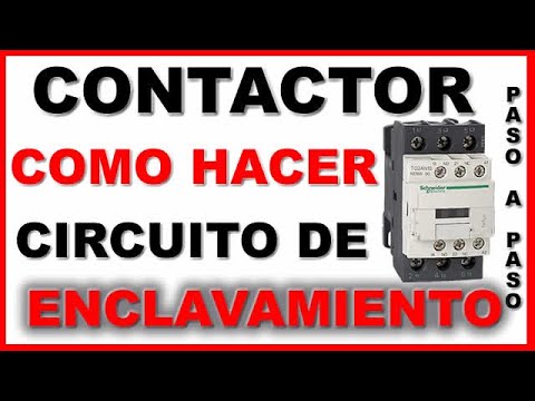
Watch the interlocking circuit lesson on YouTube.
よくある質問
Can the main contactor current rating be used for the auxiliary contact?
No. The auxiliary circuit has its own voltage, current, load type, utilization category and endurance ratings.
Is a high maximum current rating enough for a PLC input?
No. Low-level inputs may require minimum switching current or contact-reliability data in addition to maximum ratings.
Can an ordinary auxiliary contact prove the main circuit is isolated?
Not by itself. Confirm the mechanical relationship and safety architecture, and use the required independent voltage or isolation verification.
Why does DC inductive duty matter?
Interrupting an electromagnet produces stored-energy stress and arcing. Use the exact DC utilization rating and approved suppression.





