簡単な回答: An 800V EV contactor must be selected for the battery’s maximum charged voltage and transients, not the nominal architecture label. It must also satisfy insulation coordination, DC make and break duty, bidirectional current, thermal rise, precharge, short-circuit coordination, coil-driver behavior, feedback diagnostics, environmental stress, and the vehicle’s required switching life.
このエンジニアリングガイドは、バッテリーパック、BMS、テスト、調達、サービスチーム向けのレビュー可能な一連の作業へとこのトピックを変換します。このガイドは、実際の製品ファミリーを参考として使用し、すべての評価と安全上の決定は最終的な用途と現在のメーカーのドキュメントにリンクされています。.
決定マップ
| 動作状態 | 期待される証拠 | エンジニアリングへの重点 |
|---|---|---|
| Maximum working voltage | Highest charged pack plus defined operating tolerance | Use model-specific DC ratings and system transients |
| Insulation | Clearance, creepage, dielectric and pollution environment | Coordinate pack, enclosure, altitude and service access |
| Current duty | Traction, regeneration, charging and fault opening | Separate continuous, peak, make and break conditions |
| 保護 | Fuse, pyrofuse, precharge and discharge coordination | Prove fault energy and safe isolation sequence |
製品の参照と適用範囲
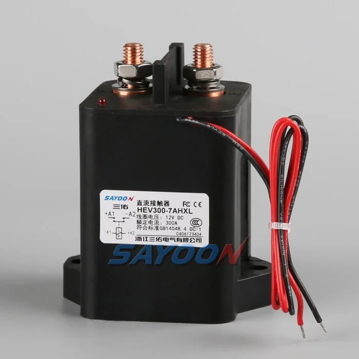
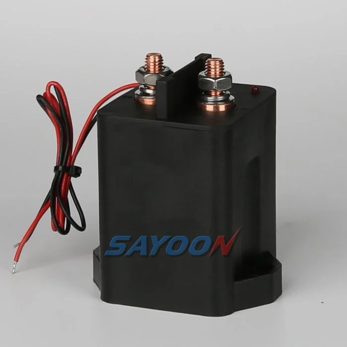
その HEV300 high-voltage sealed DC contactor ここでは、本物のSayoon製品の参考資料を示しています。レビューはこちら 高電圧DCコンタクタの範囲 隣接する電流クラスについて。画像とファミリ名は、特定の車両の承認を意味するものではありません。最終的な部品番号、コイルオプション、図面、電気的用途、絶縁性、環境適応性、耐用年数、および保護機能の調整は、合わせて検討する必要があります。.
800V is an architecture class, not one fixed voltage
An “800V” vehicle does not operate at exactly 800 V in every state. The pack voltage changes with cell chemistry, series count, state of charge, temperature, and load. Charging and regeneration can place the pack near its maximum charged voltage, while switching transients can briefly add stress. Specify the minimum, nominal, maximum continuous, and defined transient voltages.
Select the contactor using the manufacturer’s approved DC voltage conditions and insulation data. Do not approve a device merely because its name includes 800 V or because an AC insulation number looks high.
Insulation coordination and altitude
Higher voltage increases the importance of creepage, clearance, dielectric withstand, pollution degree, material group, sealing, and the distance to grounded metal. Altitude reduces air density and can require larger clearances or derating. The completed battery junction box—not the contactor alone—must maintain the required insulation under condensation, contamination, vibration, and service conditions.
Review terminal spacing, busbar geometry, mounting hardware, sensors, connector pins, and enclosure ribs. Use the standards and vehicle requirements adopted by the project; do not copy a spacing number without matching the environment and overvoltage category.
DC interruption at higher voltage
A DC arc does not naturally cross zero. At higher voltage, the contactor’s arc-control system, contact gap, opening speed, magnetic field, gas sealing, and current direction become critical. Continuous current and breaking current are different ratings. Confirm make and break performance at the maximum voltage, actual load inductance, and the required polarity or bidirectional condition.
Normal control should reduce inverter or charger current before opening when safe. Emergency opening, crash isolation, and fault interruption require separately qualified duties and protection coordination.
Thermal current and power relationships
For the same power, higher voltage can reduce current, but that does not automatically make the contactor cooler. Fast charging, launch, regeneration, enclosure temperature, terminal resistance, and busbar design still determine heating. Contact loss is approximately I²R, and joint resistance outside the contactor can become equally important.
Use measured current profiles and thermal boundary conditions. Verify temperature rise at the terminals and body with the production busbar, torque, conductor size, airflow, and neighboring fuse or pyrofuse.
Precharge and discharge
The inverter DC link must be charged through a controlled path before the main contactor closes. At 800V-class levels, the stored energy and make-current consequence are substantial. Size the resistor and precharge contactor for maximum voltage difference, capacitance, pulse energy, repeat duty, and temperature. Close the main contactor only after measured voltages meet the approved ratio and timing window.
After opening, verify that the discharge circuit reduces the load-side bus to the vehicle-defined safe threshold. A timer without voltage confirmation cannot prove the bus is safe.
Bidirectional current and charging compatibility
Traction current flows from the battery to the inverter, while regeneration and DC charging send current toward the battery. Confirm that the main contactor carries and switches the required directions. Some 800V vehicles also interact with lower-voltage chargers through a booster or reconfiguration strategy, which can create additional contactor states and switching sequences.
Map each configuration and prevent two contactors from creating an unintended parallel or series path. Add feedback and bus-voltage plausibility checks for every state.
Short-circuit and crash coordination
Define the prospective pack fault current, battery impedance, cable and busbar inductance, fuse or pyrofuse clearing behavior, and the contactor’s required withstand or interruption duty. The contactor is not a substitute for a fuse, and a fuse does not provide repeatable functional switching. The safety concept should state which device acts first and what energy remains downstream.
After a crash event, inhibit reclose, verify isolation and discharge, and require inspection of the contactor, terminals, busbars, fuse, precharge branch, and trigger circuits before service release.
Coil drive, feedback and EMC
The low-voltage coil driver must provide reliable pull-in during supply sag and controlled release during faults. Suppression changes opening time and driver stress. Capture coil current, command, auxiliary feedback, pack voltage, and load-side voltage on one time base. Use independent voltage evidence to detect welded or stuck-open main contacts.
At 800V-class switching levels, layout, shielding, grounding, and measurement isolation affect EMC and diagnostic accuracy. Validate the production harness and controller, not only a short bench setup.
RFQ and qualification checklist
Provide minimum, nominal, maximum and transient pack voltage; continuous and peak currents; current direction; make and break waveforms; DC-link capacitance; precharge and discharge requirements; short-circuit source; protection clearing time; insulation environment; altitude; temperature; vibration; sealing; coil voltage; driver and suppression; auxiliary logic; life; mounting; busbars; and required approvals.
The HEV300 shown here is a product reference. Confirm the exact voltage, current, insulation, coil, and endurance data for the final model and production installation.
受入記録
完全な部品番号、図面のバージョン、コイルオプション、端子機能、電圧範囲、電流波形、スイッチング状態、プリチャージおよび放電の詳細、ドライバーおよび抑制機能、補助ロジック、HVIL状態、保護、周囲温度および筐体温度、取り付け方向、導体およびバスバーの詳細、計測機器の位置、校正ステータス、ソフトウェアバージョン、および通過/不通過の制限値を含む1つの制御レコードを作成します。 カタログ値の測定値と異なる値を分離し、一般的な値の追加ではなく、欠落した証拠を「未処理」としてマークします。.
重要な境界におけるテスト:コイルの低圧および高圧供給、低温および高温環境、最長承認済みハーネス、繰り返しサイクル、および安全概念に記載された異常状態。一次基準時間でコマンド、コイル電圧および電流、補助フィードバック、パック電圧、負荷側電圧、および障害フラグの記録。説明不明な不適合後に自動再試行を停止、蓄電されたエネルギーを隔離、および最初の障害の証拠を保持する。セットアップと端子配置の写真を撮影し、すべてのプローブポイントを識別し、保管されたハーネスおよびバスバーを記録し、各しきい値が安全である理由を説明する。熱安定化後の代表的なサンプルと計画された耐久ブロック後のサンプルを繰り返す。オペレータ、テスト日、サンプル識別、および生産アセンブリからのすべての逸脱を記録する。後続の正常なサイクルで同様の基準値と比較できる。これらは、交換サンプル、サプライヤーの修正、ファームウェアのアップデート、またはハーネスの変更を、同様に承認された基準値と比較できるようにする。.
Also verify labeling, service documentation, isolation points, and change-control approvals before the production design is released to vehicle assembly.
関連するSayoonガイド
使用する DCコンタクタ選定ガイド, セーフコンタクターテストワークフロー, 、および 開閉時間ガイド 補完的な決定のため。 feedback plausibility guide explains command, auxiliary, and bus-voltage correlation.
教育ビデオ
WHAT IS 800-Volt Architecture in EVs? by EV Zone provides visual background related to this engineering review. It does not replace the written requirements, product data, or vehicle safety procedure.
よくある質問
What is the most important check for 800v ev contactor?
最大電圧と実効スイッチング波形から始め、その後、正確なコンタクタデータ、制御シーケンス、設置、および故障挙動を確認します。.
補助連絡担当者がメイン連絡担当者が健康であることを証明できるだろうか?
いいえ。補助フィードバックレポートの仕組みは限界にまで限定されています。バス電圧、タイミング、コイル電流、および回路状態を独立した証拠として使用してください。.
定格電流を完全な選択基準として使用することは可能でしょうか?
いいえ。連続電流、誘導電流、断路電流、電圧、温度、極性、寿命、絶縁性、および保護の調整は、別々の条件です。.
RFQとともに送付すべき情報は何か?
電圧および電流の波形、スイッチングシーケンス、環境、コイルおよびドライバの詳細、フィードバックロジック、保護、取り付け、耐用年数目標、および必要な試験証拠を送信してください。.
権威ある参考文献
- SAE J1766 electric and hybrid vehicle safety practice
- テキサス・インスツルメンツ、EVおよびHEV用の高電圧コンタクタを開発
- NHTSA electric-vehicle safety information
- Berkeley power electronics technical report
車両プログラムで採用された仕様および要件を使用してください。標準やサプライヤーのデータは変更される場合があります。責任あるエンジニアリングチームは最終設計を確認する必要があります。.





