Snel antwoord: A robust HVIL strategy prevents a main contactor from closing when the interlock is open, opens the contactors when a valid interlock is lost, and verifies that the load-side bus has discharged before service access. The software should distinguish an intentional service opening from a broken wire or connector, but all unsafe states must inhibit high-voltage operation.
HVIL contactor control is a sequence problem: the high-voltage interlock loop tells the controller whether covers, connectors, service plugs, and related safety links are closed, while contactor commands connect or isolate the battery. HVIL is not a replacement for contactor feedback and it is not a high-voltage measurement. It is a low-voltage permission and fault signal that must be interpreted with the pack state.
At-a-glance design map
| Element | What it does | Selection or diagnostic focus |
|---|---|---|
| HVIL loop | Series low-voltage continuity through covers and plugs | Permission and tamper/fault indication |
| Contactor command | High-side or low-side coil driver output | Requests mechanical state; does not prove it |
| Aanvullende feedback | Mechanism-position contact | Confirms movement with debounce and plausibility |
| Bus sensing | Pack and load-side voltage measurements | Confirms electrical isolation and discharge |
Productreferentie en toepassingsgebied
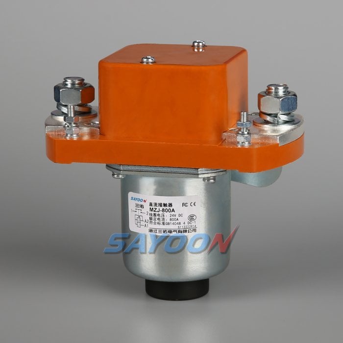
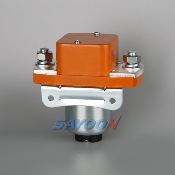
The MZJ-800A normally-open DC contactor shown in this article is a real Sayoon product reference. See the MZJ-800A normally-open DC contactor product page en de Uitgebreid assortiment hoogspannings-DC-contactoren for the family context. The image does not replace a model-specific drawing review; voltage, coil, current, insulation, duty, and mounting must be confirmed for the application.
What HVIL can and cannot prove
An HVIL circuit normally runs a monitored low-voltage signal through high-voltage connectors, covers, service disconnects, and sometimes coolant or battery junction-box interfaces. Opening one item interrupts the loop. The controller can then inhibit new contactor commands or open an already closed path. This protects technicians from a connector being opened while the pack is still actively driving the bus.
HVIL continuity does not prove that a main contactor opened, that a fuse is intact, or that the bus is at zero volts. A welded contactor can exist with a healthy HVIL loop, and a broken HVIL wire can exist with perfectly healthy contactor contacts. Keep the three signals—interlock, mechanism feedback, and voltage—separate in the design and diagnostics.
Recommended control sequence
At wake-up, check HVIL, service-disconnect state, isolation status, and pack diagnostics before energizing any coil. If the path is valid, run precharge, monitor the DC-link rise, close the main contactor, and verify auxiliary feedback. When HVIL opens, remove the close permission immediately, command the contactors open according to the approved fail-safe strategy, and start a discharge timer. The system should not report “safe” until the measured voltage and time conditions are satisfied.
The order matters. A fixed delay before opening can leave energy present if a converter is sourcing the bus. Conversely, opening a contactor while a large current is flowing can increase arc stress. The controller should use the measured state and hardware protections rather than relying on a single software timer.
Debounce, diagnostics and fault ownership
Connectors vibrate and service plugs can bounce during insertion. Debounce HVIL transitions in a way that cannot mask a real open event, and record raw and filtered state. A persistent open loop should identify the segment or connector if the harness supports localization. A sudden open during drive should latch a high-voltage interlock fault, store the state of contactor commands and feedback, and prevent an automatic reclose until the service procedure allows it.
Do not let a noisy auxiliary contact clear an HVIL fault. Each diagnostic input should have a defined owner: the interlock monitors physical access paths, auxiliary contacts monitor mechanism position, and voltage sensing monitors electrical energy. This separation makes root-cause analysis faster.
Driver hardware and polarity
The coil-driver architecture can be high-side, low-side, or a dedicated automotive switch. Verify coil polarity, suppression, current limiting, open-load detection, short-to-battery and short-to-ground behavior, and the driver’s response when HVIL drops. A flyback diode can slow release; an active clamp or economizer changes the waveform. Validate the selected network with the exact contactor coil and harness.
The MZJ-800A reference shown here is a normally-open product example. Its coil option, auxiliary arrangement, and allowable suppression must be confirmed from the ordering code and drawing. Do not infer a safe release time from a different coil voltage or model.
Contactor feedback versus HVIL
A healthy close sequence should satisfy all of the following: HVIL remains valid, the coil command is present, the auxiliary contact changes within the expected time, and the load-side voltage follows the precharge and main-close profile. If HVIL is valid but auxiliary feedback is missing, investigate the coil, driver, mechanism, wiring, and contact rating. If both feedback and command look correct but voltage is wrong, investigate the main path, fuse, precharge branch, or measurement.
On opening, a valid HVIL loop does not permit the software to assume zero energy. Confirm the auxiliary transition and the bus discharge threshold. This layered plausibility check also catches a welded main contactor that would otherwise hide behind a normal HVIL signal.
Service and crash behavior
A service disconnect may open the HVIL before the main contactors can be commanded. The pack should enter a defined sequence: remove torque permission, open contactors if possible, discharge the bus, and communicate the remaining voltage to the service tool. A crash controller may require a faster hardware path, such as a pyrofuse trigger, but the HVIL state still helps prevent re-energization during recovery.
Write the timing and ownership into the system safety concept. The signal source, pull-up, diagnostic coverage, and default state should be clear to the person troubleshooting the pack months later.
Commissioning checklist
With the pack de-energized, verify every HVIL segment and connector pin. With current limited, open one segment at a time and confirm that no close command is accepted. Exercise precharge and main close while recording HVIL, commands, auxiliary feedback, source voltage, load voltage, and timestamps. Then remove the interlock during an approved controlled test and verify contactor opening, discharge, fault latching, and recovery behavior.
Use lockout and the vehicle maker’s service instructions. The related Sayoon guides on safe contactor testing and opening/closing time are useful references, but neither replaces the vehicle-specific safety procedure.
Acceptance record for the engineering team
Before approving this hvil contactor control decision, create one controlled record that can be read by the design engineer, test engineer, production team, and service technician. List the exact part number and coil option, drawing revision, terminal labels, bus voltage range, current waveform or duty profile, ambient and enclosure temperatures, mounting orientation, conductor size, terminal torque, driver and suppression details, auxiliary logic, HVIL state, measurement instruments, calibration dates, and the pass/fail thresholds. Separate catalogue values from measured values and identify every assumption. If a value is not available, mark it as an open engineering action instead of filling the gap with a typical number.
Run the sequence at the boundaries that matter: minimum and maximum low-voltage supply, cold and warm equipment, the longest approved harness, repeated cycles, and the abnormal state that the safety concept names. Capture command, coil current, feedback, pack voltage, load-side voltage, and fault flags on one time base. After a failed event, stop automatic retries, isolate stored energy, and preserve the first-fault data. A later successful cycle does not erase evidence of a welded contact, slow release, intermittent interlock, or driver protection event. Release the product only when the complete record is reviewed against the current data sheet and vehicle-level requirements. Include photographs of the terminal layout and probe locations, the software build and calibration state, and a short explanation of why the chosen threshold is safe. This makes the result repeatable when a replacement sample, new harness, or firmware revision is introduced.
Related engineering guidance
Gebruik de Selectiehandleiding voor DC-relais for the broader sizing workflow, the safe contactor test guide for isolation and measurement, and the Gids voor openingstijden en sluitingstijden when setting diagnostic windows. For PLC-connected control logic, see the PLC-stroomregelaar. These internal links support the decision without replacing the device data sheet or the vehicle safety procedure.
Educatieve video
This neutral training video is included for visual context. It is not a product endorsement and the written, model-specific requirements above control the engineering decision.
Bekijk de educatieve video op YouTube.
Veelgestelde vragen
What is the first check for hvil contactor control?
Confirm the exact command, supply, coil option, and safe measurement points before energizing anything. Then compare the expected feedback and bus-voltage response with the approved sequence.
Can auxiliary feedback prove the main contacts are healthy?
No. It reports mechanism position within its own limits. Combine it with load-side voltage, timing, and the documented circuit state.
Can I use a generic contactor driver or suppression diode?
Only after the coil, driver, polarity, release time, EMC, and protection behavior are approved together. A generic change can create slow release or false diagnostics.
Wat moet er in een offerteaanvraag (RFQ) staan?
Provide voltage, current waveform, switching duty, temperature, mounting, coil voltage, suppression, feedback, insulation, life, and the required drawings and test evidence.
Sources and standards context
- Rockwell Automation interlock application information
- Siemens 3RT2 contactor manual
- OSHA-vereisten voor werkzaamheden aan elektrische installaties
Standards, safety rules, and supplier ratings change by market and product revision. Use the current edition adopted by the project and obtain the full requirements through the responsible engineering and compliance process.





