In the electrical machinery manufacturing industry, the DC contactor serves as the core switching element in DC motor control circuits. Its proper selection and operational reliability directly impact the failure rate and maintenance costs of new energy equipment, electric vehicles, energy storage systems, and industrial automation devices. Today, professional users face challenges that have evolved from “whether it can switch on and off” to “whether it can maintain hundreds of thousands of switching cycles under harsh conditions”—driving manufacturers to innovate in contact materials, arc extinguishing systems, and permanent magnet optimization.
The global DC contactor market is undergoing structural growth. Electric vehicles and charging infrastructure have generated massive demand for high-voltage DC contactors (≥750V DC). Energy storage systems and photovoltaic inverters have made high-current DC switching components a necessity. According to TechSci Research, the global DC contactor market was valued at approximately USD 520.7 million in 2024 and is expected to reach USD 806.3 million by 2030, growing at a CAGR of 7.40%.1 (This figure focuses on industrial general-purpose and definite-purpose DC contactors; the broader market including automotive high-voltage contactors is estimated at nearly double this value by other industry trackers.) Another authoritative market study published by Mordor Intelligence corroborates this outlook, estimating the market at around USD 5.3 billion in 2024 with a projected CAGR of approximately 7.5% through 2030, underscoring the consensus on robust demand. In China, the high-voltage DC contactor market alone reached approximately RMB 10.1 billion in 2025, with electric vehicles accounting for the largest share.
For professional users, selecting the correct DC contactor is not only the foundation for ensuring continuous production but also a critical element of life-cycle cost management. Common selection errors—mismatches between rated current and utilization category, coil voltage compatibility issues, and inadequate arc extinguishing methods—often lead to contact welding, coil burnout, or unplanned shutdowns.
1 TechSci Research report “DC Contactor Market – Global Industry Size, Share, Trends, Opportunity, and Forecast, 2020-2030F” (June 2025). Market estimates cover general-purpose and definite-purpose DC contactors across industrial, renewable energy, and select automotive applications.
Understanding DC Contactor Basics: Function and Core Components
A DC contactor is an electromagnetic switching device suitable for remote, frequent making and breaking of DC main circuits. Unlike AC contactors, DC contactors face a more severe arc extinguishing challenge—DC arcs have no natural current zero-crossing point and must be forcibly extinguished immediately after contact separation.
Its core functions are accomplished by four systems:
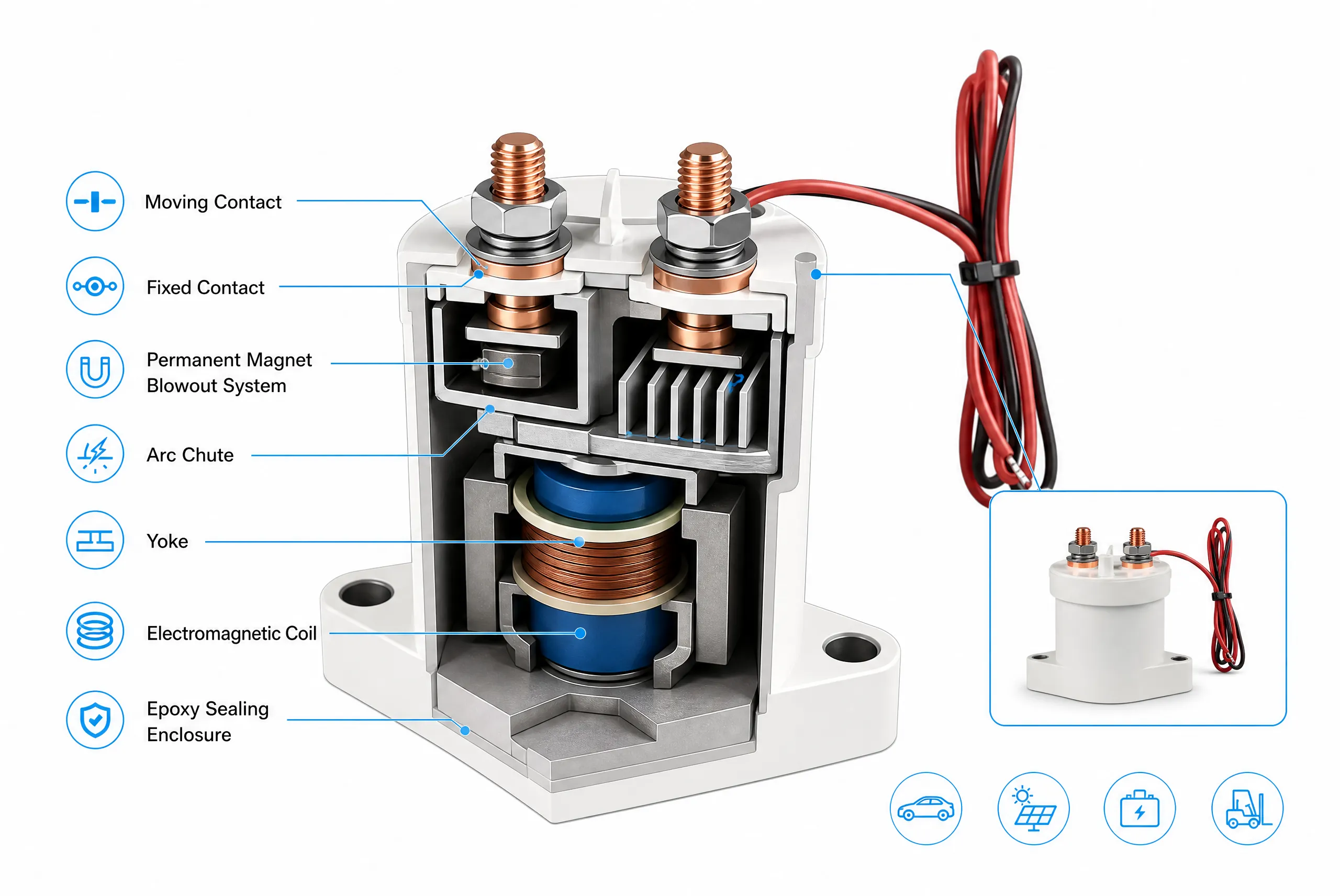
Electromagnetic System: Comprising the coil, yoke, and return spring. When DC control voltage is applied, electromagnetic force pulls in the moving yoke, driving contacts to close. DC coils rely on resistance to limit current, with no inrush current peaks, resulting in smoother response.
Contact System: Main contacts (single-pole or double-pole) and auxiliary contacts (for signal feedback). Contact material directly determines electrical life—AgSnO2 offers superior anti-welding performance for inductive loads, while AgNi provides cost-effectiveness in low-to-medium current applications (≤100A).
Arc Extinguishing System: The most critical difference from AC contactors. Common methods include permanent-magnet blow-out (suitable for ≤200A), magnetic blow-out coil (for high-current heavy-duty), and gas-assisted extinction. Permanent-magnet blow-out is industry mainstream, but magnet temperature stability (-40°C to +125°C) directly affects long-term performance. Research on permanent-magnet blow-out has shown that increasing magnetic flux density up to approximately 60 mT significantly reduces arc duration, with diminishing returns beyond this threshold.2 The magnetic field required for effective blow-out in a 48V DC system with L/R ≤ 15ms typically falls in the range of 50–150 mT at the contact surface, depending on contact gap and arc chamber geometry. Samarium-cobalt (SmCo) offers superior high-temperature stability over neodymium-iron-boron (NdFeB), maintaining over 90% of its room-temperature magnetic flux at 125°C, compared to approximately 85% for NdFeB.
Insulation and Sealing System: High-voltage applications require epoxy potting or ceramic sealing to ensure dielectric performance under vibration, humidity, and salt spray. Potting material must meet CTI ≥600V and UL94 V-0 flame retardancy.
2 These findings draw from multiple published investigations, including the experimental work by Wang et al. (see References) that systematically examined permanent magnet effects on DC arc duration in sealed contactors. The required magnetic field varies with contact gap, arc chamber geometry, and circuit time constant (L/R).
Specification Parameters: What Professional Users Must Verify
Rated Operational Current (Ie) and Overload Capability
- Continuous current: Select at 1.2–1.5× load rated current
- Short-time overload: Motor starting current is 3–6× Ie; contactor must withstand without welding
- Temperature derating: For every 10°C rise, current capacity decreases ~1.5–2%6
Rated Operational Voltage (Ue) and Insulation Voltage (Ui)
- Common grades: DC 12V–1500V depending on application
- Breaking capacity: Specified under L/R = 1ms or 15ms inductive load; verify against actual circuit time constant
Coil Control Voltage and Power Consumption
- Pick-up voltage: typically 60–70% of rated voltage
- Drop-out voltage: typically 10–30% of rated voltage
- Energy-saving holding technology can reduce holding power by 60–80%
Mechanical and Electrical Life
- Mechanical life: 500,000–1,000,000+ operations (no load)
- Electrical life: 10,000–100,000 operations (under load, depends on duty category)
Mounting Dimensions and Terminals
- Verify cabinet space, terminal specifications, and mounting method
6 The 1.5–2% derating coefficient per 10°C rise is an empirical range derived from copper resistivity temperature dependence and insulation thermal aging characteristics. Exact values differ by manufacturer design and must be verified against official datasheets.
From Core Manufacturing Processes to Quality Assurance
Key Materials
- Contacts: AgSnO2 for DC-3/DC-5 inductive loads; AgNi for cost-effective low-current applications
- Permanent Magnets: NdFeB (higher energy product, ≤80°C) or SmCo (better temperature stability, up to 150°C)
- Coil Insulation: Class F (155°C) or Class H (180°C) magnet wire
Core Manufacturing Processes
1. Coil Winding & Vacuum Impregnation: Precision winding with tension controlled within ±3%; vacuum impregnation eliminates air gaps and enhances heat dissipation. In high-volume production, process capability indices (Cpk) are commonly used to monitor critical parameters. Coil winding tension is monitored in real-time with closed-loop control, maintaining a Cpk ≥ 1.337 across production batches.
2. Yoke Machining & Heat Treatment: Pole faces ground to Ra ≤1.6μm; annealing removes cutting stresses.
3. Contact Riveting & Welding: Shear force ≥300N, contact resistance ≤0.1mΩ; monitored by online CCD inspection. For contact resistance, a Cpk ≥ 1.67 is typically required for automotive-grade products, indicating that less than 0.6 parts per million fall outside specification.
4. Permanent Magnet & Arc Chamber Assembly: Precise positioning ensures uniform blow-out effect; grid spacing tolerance ±0.1mm.
5. Final Assembly & Sealing: Epoxy potting or ceramic sealing with helium leak testing (≤1×10⁻⁹ Pa·m3/s).
Quality Assurance Framework
EOL testing (100% of production) includes:
| Test Item | Condition | Acceptance |
|---|---|---|
| Withstand voltage | AC 2500V/DC 3500V, 1 min | No breakdown, leakage ≤5mA |
| Insulation resistance | DC 1000V megger | ≥50MΩ |
| Pick-up/drop-out voltage | 0.6Us / 0.1–0.3Us | Reliable operation |
| Contact resistance | 4-terminal micro-ohmmeter | Per specification |
| Electrical life (spot check) | DC-3 duty | ≥Rated value |
| Temperature rise (spot check) | 1.0Ie continuous | ≤Specified limit |
All testing protocols align with IEC 60947-4-1:2023 (the fifth edition, which cancels and replaces the 2018 fourth edition)3 and GB/T 14048.4-2020 (the national standard equivalent adopting IEC 60947-4-1)4. The national standard applies to contactors whose main contacts are used for circuits with rated voltage up to AC 1,000 V or DC 1,500 V. Furthermore, compliance with UL 60947-4-1 ensures that temperature-rise limits and dielectric withstand requirements are harmonized with North American safety expectations, an important consideration for OEMs exporting to multiple regions.
For manufacturers serving automotive and industrial sectors, third-party certifications provide an additional layer of quality assurance. Recognized certifications include ISO 9001 for quality management systems, IATF 16949 for automotive-grade manufacturing, and product-specific certifications such as UL 60947, CCC (China Compulsory Certification), and CE marking. These certifications require regular surveillance audits and independent testing, offering buyers verifiable evidence of manufacturing capability.
3 IEC 60947-4-1:2023 Low-voltage switchgear and controlgear – Part 4-1: Contactors and motor-starters – Electromechanical contactors and motor-starters. International Electrotechnical Commission, Geneva, 2023.
4 GB/T 14048.4-2020, Low-voltage switchgear and controlgear – Part 4-1: Contactors and motor-starters – Electromechanical contactors and motor-starters (including motor protectors). Standardization Administration of China, 2020. (Identical to IEC 60947-4-1:2018 at time of issuance.)
7 Cpk, the process capability index, is defined as min{(USL-μ)/3σ, (μ-LSL)/3σ}. A Cpk of 1.33 corresponds to approximately 63 defects per million opportunities. Automotive industry guidelines (IATF 16949) frequently require Cpk ≥1.67 for safety-related special characteristics, equating to less than 0.6 ppm defects.
OEM and Customization Options for Professional Buyers
Common customization requirements include:
| Parameter | Typical Scenario | Certification Impact |
|---|---|---|
| Coil voltage (non-standard) | Adapt to specific control system | Yes (4–8 weeks for re-verification) |
| Terminal form/location | Fit limited cabinet space | No |
| Auxiliary contact configuration | Specific logic requirements | No |
| Mounting dimensions | Match existing hole patterns | No (verify structural strength) |
| Labeling and packaging | Brand consistency | No |
| High-voltage/non-standard grades | Special applications | Yes (full type tests, 8–12 weeks) |
Per IEC 60947-4-1:2023, utilization categories (DC-1, DC-3, DC-5, etc.) describe the nature of the load and switching duty—resistive, inductive, starting motors, or frequent switching. When OEM changes affect these parameters, partial type tests must be re-verified. Manufacturers should provide a Certification Impact Assessment Report clearly listing affected standard clauses, test items, cost estimates, and timeline. This transparency helps customers balance functional requirements, delivery speed, and compliance costs.
A 5-Step Selection Checklist
Step 1: Confirm Utilization Category
Per IEC 60947-4-1:2023, DC utilization categories are defined as follows:
| Category | Typical Load | Making/Breaking Current | Margin |
|---|---|---|---|
| DC-1 | Non-inductive or slightly inductive loads, resistance furnaces (L/R ≤ 1ms) | 1×Ie | 1.0–1.1× |
| DC-3 | Shunt motors: starting, plugging, inching (L/R ≤ 2.5ms) | 4–6×Ie / 1×Ie | 1.2–1.5× |
| DC-5 | Series motors: starting, plugging, inching (L/R ≤ 15ms) | 4–6×Ie / 4–6×Ie | 2.0–3.0× |
| DC-13 | Electromagnets, solenoids (L/R ≤ 3ms) | 1×Ie | 1.0–1.2× |
Step 2: Calculate Current and Overload Capability
Select at 1.2–1.5× actual load current. Verify short-time withstand capability matches motor start duration.
Step 3: Verify Coil Voltage and Power Consumption
Confirm voltage matches control system. For dense installations, select models with energy-saving holding.
Step 4: Verify Arc Extinguishing and Breaking Capacity
Confirm breaking capability under actual L/R time constant. For high-current DC applications, prioritize permanent-magnet blow-out with arc chamber design.8
Step 5: Verify Mounting Dimensions and Environmental Suitability
Check cabinet space, terminal fit, and operating temperature range. At altitudes above 2,000m, derate per IEC 60947-1 (1–2% per 100m). According to IEC 60664-1 (insulation coordination) and GB/T 16935.1, the reduced air density at high altitudes lowers dielectric strength, mandating increased clearance distances and corresponding current derating factors, typically 1–2% for every 100m beyond 2,000m.
8 Permanent-magnet DC contactors are polarized devices. The main terminals are marked “+” and “−”. Reverse connection can prevent the arc from being driven into the arc chute, severely compromising breaking capacity. Always verify polarity during installation.
Application Case — DC Contactor Selection for AGV Traction Systems
A Southeast Asian AGV manufacturer developing a 5-ton capacity vehicle faced contactor welding issues. The 48V system used an 8kW traction motor (peak 16kW). Initial selection of a 200A contactor (based on steady-state current: 8000W/48V ≈ 167A) failed within 300 cycles during frequent start-stop operation on inclines.
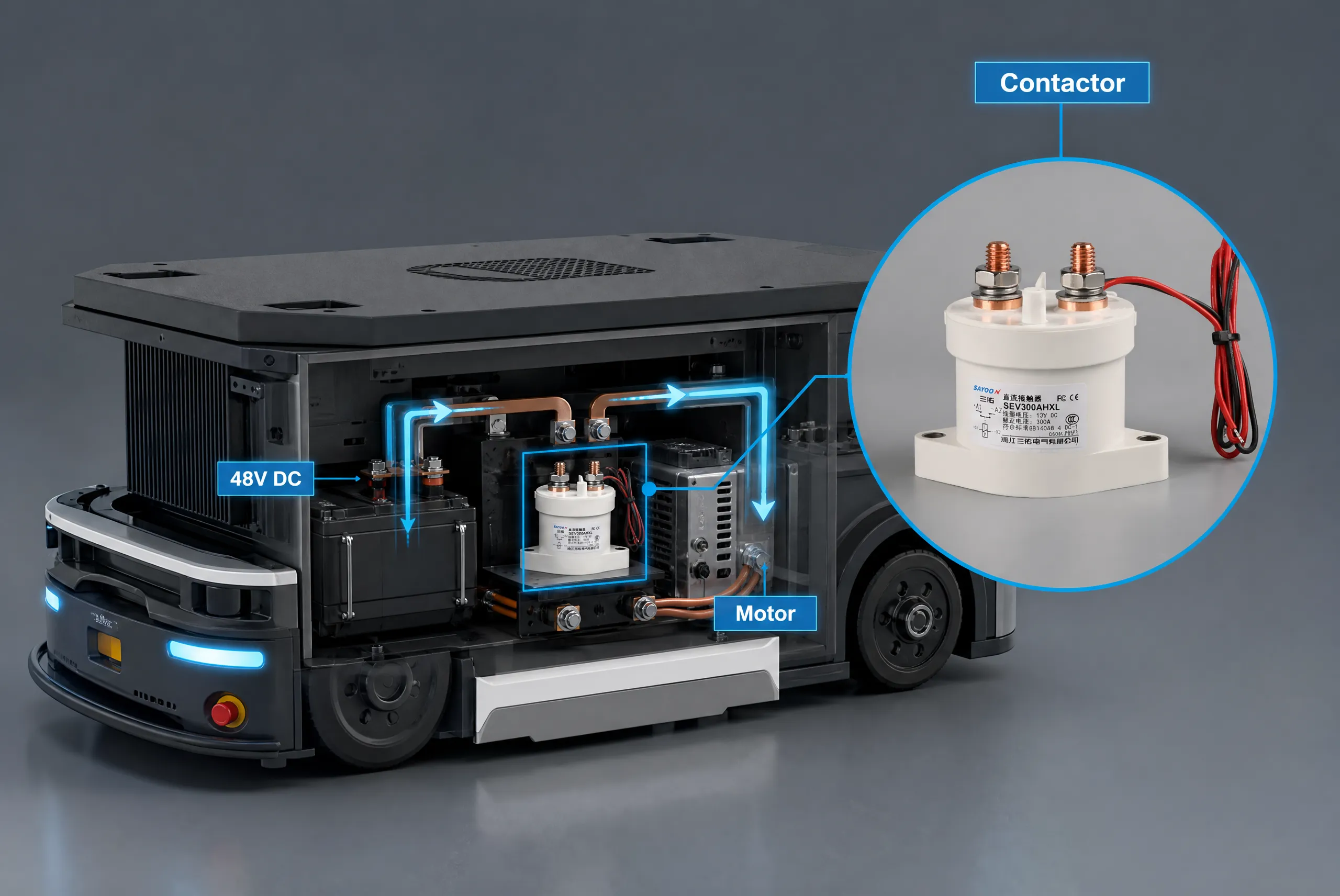
Solution using the 5-step checklist:
- Utilization Category: The application involved frequent starting, plugging, and inching—clearly DC-5 (not DC-1). Per IEC 60947-4-1:2023, DC-5 requires making 4–6×Ie and breaking 4–6×Ie.
- Current Rating: Peak starting current reached ~1000A for 3–5 seconds. A 300A continuous-rated contactor was required (167A × 1.5 margin = 250A minimum; 300A provides additional thermal margin). Short-time overload capacity needed ≥1000A for 5 seconds.
- Coil Voltage: The AGV control system operated at 24V DC. The customer selected a dual-coil configuration (magnetic latching) to minimize battery drain during holding.
- Arc Extinguishing: The 48V system with L/R ≈ 8ms required verified DC-5 breaking capacity at 48V.
- Mounting: Limited space required compact form factor with busbar connections; ambient temperature range -10°C to +45°C required F-class insulation.
Selected Specification:
- Model: CZW-300A-48V-DC5 (customized configuration)
- Contact configuration: 1NO (SPST)
- Coil: 24V DC, dual-coil magnetic latching
- Terminal type: M8 busbar, vertical orientation
- Ambient temperature rating: -25°C to +55°C
- Insulation class: Class F (155°C)
- Verified breaking capacity: 1200A at 48V DC, DC-5, L/R = 8ms
Outcome: The customer selected the CZW series DC contactor (300A continuous, ≤80V, magnetic latching option). After 6 months and over 80,000 start-stop cycles, zero contactor-related failures were reported. Unplanned maintenance interventions dropped from 2–3 times per month to zero.5
5 Case based on field data from a Southeast Asian logistics equipment manufacturer, 2024. The CZW series contactor is rated for DC-5 utilization category per IEC 60947-4-1:2023 and is commonly applied in AGV, electric forklift, and battery switching applications. Individual results may vary based on specific operating conditions.
FAQ: Frequently Asked Questions
Q1: Core structural difference between DC and AC contactors?
DC contactors require permanent-magnet or magnetic blow-out systems because DC arcs have no natural zero-crossing; AC contactors use simpler grid-type arc chutes.
Q2: Permissible coil voltage fluctuation range?
85–110% of rated voltage per IEC 60947-4-1:2023. Pick-up voltage is typically 60–70% Us, drop-out 10–30% Us.
Q3: How to determine if a contactor needs replacement?
(1) Contact erosion depth >0.5mm or area loss >30%; (2) Contact resistance >50% above initial value; (3) Coil resistance deviates >±15% from nominal.
Q4: Is there demagnetization risk for permanent magnets?
Yes at high temperatures. NdFeB has upper limit of 80–100°C; SmCo up to 150°C. Verify manufacturer’s temperature stability screening.
Q5: Difference between DC contactor and DC relay?
Contactors switch high-current main circuits (≥10A) with arc chambers; relays switch control signals (≤5A) without dedicated arc extinguishing. Not interchangeable.
Q6: Can different brands with same rating be interchanged?
No. Verify mounting dimensions, terminal type/center spacing, coil voltage, auxiliary contact configuration, and breaking capability under actual L/R conditions.
Q7: Selection considerations for high operating frequency?
Check electrical life vs. frequency limits; select Class H insulation; consider energy-saving holding to reduce heat generation.
Q8: Causes of excessive coil temperature rise?
(1) Coil voltage below pick-up threshold; (2) Contaminated yoke surfaces; (3) Ambient temperature exceeds design limit; (4) Continuous holding without energy-saving module.
Buyer’s Guide
How to Obtain: Fill in your company name, job title, and work email below. The download link will be sent within 24 hours.
This article is prepared based on IEC 60947-4-1:2023 and GB/T 14048.4-2020 standards as a technical reference for professional users. Specific selection should be based on official datasheets and actual project conditions.
References
- IEC 60947-4-1:2023, Low-voltage switchgear and controlgear – Part 4-1: Contactors and motor-starters – Electromechanical contactors and motor-starters. International Electrotechnical Commission, Geneva, 2023.
- GB/T 14048.4-2020, Low-voltage switchgear and controlgear – Part 4-1: Contactors and motor-starters – Electromechanical contactors and motor-starters (including motor protectors). Standardization Administration of China, 2020.
- TechSci Research, DC Contactor Market – Global Industry Size, Share, Trends, Opportunity, and Forecast, 2020-2030F, June 2025.
- Mordor Intelligence, DC Contactor Market Size & Share Analysis – Growth Trends & Forecasts (2025-2030), 2025.
- Y. Wang, X. Li, et al., “Influence of Permanent Magnet Configuration on DC Arc Extinction in Contactors,” IEEE Transactions on Plasma Science, vol. 47, no. 5, pp. 2456-2463, May 2019.
- GB/T 16935.1-2023, Insulation coordination for equipment within low-voltage systems – Part 1: Principles, requirements and tests. Standardization Administration of China, 2023.
About the Manufacturer
This article was prepared by the technical team of Zhejiang Sayoon Electric Co., Ltd. Since its establishment in 1998, Sayoon has specialized in the development and manufacturing of DC contactors and electrical control components, with particular expertise in permanent-magnet blow-out design for DC-5 (series motor) applications up to 3000A and 80V. The company maintains ISO 9001 certification and offers UL, CCC, and CE certified products. Core product lines include the SZJ series (50–1500A, ≤60V) covering NO and NC configurations for electric forklifts and communication base stations, and the CZW series (50–3000A, ≤80V) featuring 1NO, 1NC, 1NO1NC, SPDT, DPDT, and magnetic latching options for electric vehicles, electroplating, and high-power motor applications. Through continuous technical improvement and manufacturing experience accumulation—including in-house coil winding with closed-loop tension control and fully automated EOL testing—Sayoon is committed to providing reliable products, practical solutions, and responsive support for professional industrial users worldwide. For further technical information or product selection support, please contact our technical team via the official website.





