HV battery contactor sequencing closes a precharge path first to limit inrush onto capacitive DC buses, verifies the bus reaches a defined voltage threshold within a timeout, then commands main contactors to close — with device roles, feedback, and fault reactions documented on one sequence chart.
This explainer is for BMS, EMS, and commissioning engineers who must document energisation order on BESS and mobility battery paths. For disconnect-path device selection, see HV contactor selection for EV battery disconnect. Browse HEV Series HV DC contactors when mapping main-path SKUs.
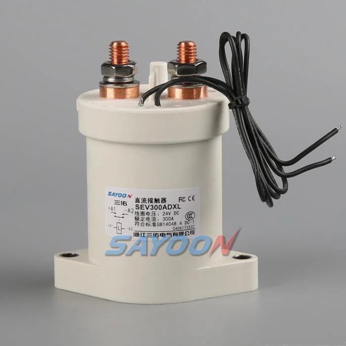
Part 1. What roles do precharge and main HV battery contactors play?
HV battery contactors on main paths carry pack or container bus current after the system is energised. A precharge branch — often a contactor plus resistor or active limiter — charges DC-link capacitance through a controlled path before main contacts close. The two roles are related but not interchangeable on the schematic.
| Element | Typical role | Document on sequence chart |
|---|---|---|
| Precharge contactor | Connect precharge resistor/limiter to bus | Close order, timeout |
| Precharge resistor / limiter | Restrict inrush current | Resistance or current cap |
| Main HV contactor | Galvanically connect battery to bus | Close after threshold |
| Auxiliary contacts | Report main state | Feedback to BMS/EMS |
| Voltage sense | Confirm bus potential | Threshold and debounce |
The high-voltage system overview at BatteryDesign.net notes precharge before main contactors close onto capacitive links — treat as architecture expectation to verify on your diagram.
Part 2. Why must precharge finish before main contactors close?
Closing main contactors onto an uncharged capacitive DC bus draws inrush current that can trip protection, damage contacts, or produce voltage collapse that faults the PCS or inverter front end. Precharge raises bus voltage through a resistive or controlled path so mains close onto a partially equalised potential.
If your programme also sizes container main devices, cross-read battery contactor sizing for commercial BESS containers for RFQ inputs — sequencing and sizing are separate deliverables.
Inrush factors integrators record
- Total capacitance on the DC bus at the contactor node
- Maximum allowable precharge current
- Battery string voltage available during precharge
- Cable inductance and sense point location
Resistor-based precharge designs trade duration against heat dissipation. Active limiters add control complexity but can shorten energisation time when software and hardware limits are aligned. Either approach still requires a defined timeout so the EMS does not hold a precharge contactor closed indefinitely against a failed PCS or open fuse.
Document whether precharge is attempted on every wake-up event or only after long shutdown intervals. Repeated partial precharge attempts without mains close can accumulate contact wear on the precharge branch even when main contacts never switch.
Part 3. How are voltage thresholds and timing limits set?
Threshold voltage defines when the bus is close enough to battery potential for main contactors to close safely. Timeout defines how long precharge may run before the sequence aborts and diagnostics flag a fault.
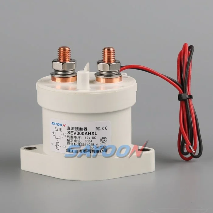
Typical documentation fields
| Field | Purpose | Example record |
|---|---|---|
| V_precharge_target | Bus voltage to permit main close | 95% of pack voltage |
| t_precharge_max | Abort if threshold not met | 3 s |
| I_precharge_limit | Cap resistor path current | Supplier study value |
| V_sense_node | Where threshold is measured | PCS DC+ after fuse |
EVolve Library’s HV battery architecture notes discuss sequenced energisation — useful vocabulary for sequence charts, not a substitute for your platform thresholds.
Part 4. How does BMS or EMS logic execute the sequence?
Control logic typically executes: interlocks satisfied → precharge contactor commanded closed → voltage and current monitored → threshold met → main contactor commanded closed → precharge path opened → auxiliary feedback validated.
State machines should define:
- Preconditions — isolation confirmed, no active faults, temperature limits OK
- Precharge command — driver output, timeout start
- Threshold check — filtered voltage comparison with hysteresis
- Main close — only if threshold and current limits pass
- Precharge open — remove resistor path after mains confirmed
- Fault reaction — open mains, log code, require service routine
Software teams should version sequence charts with firmware releases. A threshold change without updating the chart invalidates prior commissioning logs and creates field confusion between engineering and service teams.
Redundant main contactors add parallel monitoring requirements: document which pole closes first, how asymmetry is detected, and whether both auxiliaries must agree before the PCS enable line asserts.
Part 5. What commissioning checks prove sequencing works?
Commissioning should capture bus voltage versus time, precharge current decay, main auxiliary state, and fault injection results — not only a single successful close.
Minimum test log
| Test | Pass criteria | Fail indicator |
|---|---|---|
| Normal precharge | Threshold within t_max | Timeout fault |
| Main auxiliary feedback | Matches commanded state | Mismatch fault |
| Precharge abort | Mains remain open | Main welded or closed early |
| Repeated cycle | Stable wear within plan | Over-temperature or weld |
Field teams should store oscilloscope or data-logger captures with EMS timestamps so software timeouts can be correlated with measured bus voltage. This evidence becomes the baseline when suppliers or firmware updates change threshold constants.
For BESS commissioning integration context, align with the HVDC contactor integration checklist for BESS where main-path checks overlap.
Part 6. What should appear on a precharge sequence chart for RFQ?
| Sequence step | Owner | Feedback required |
|---|---|---|
| Interlocks cleared | BMS/EMS | Digital inputs listed |
| Precharge close | BMS/EMS | Current or voltage trace |
| Threshold met | BMS/EMS | Sense node documented |
| Main close | BMS/EMS | Auxiliary contact |
| Precharge open | BMS/EMS | Resistor path de-energised |
| Fault reaction | BMS/EMS | Safe state defined |
Main-path SKU examples such as published SEV300AH parameters address continuous current and voltage class — they do not, by themselves, define precharge resistance or timing. Submit those values separately when requesting supplier review.
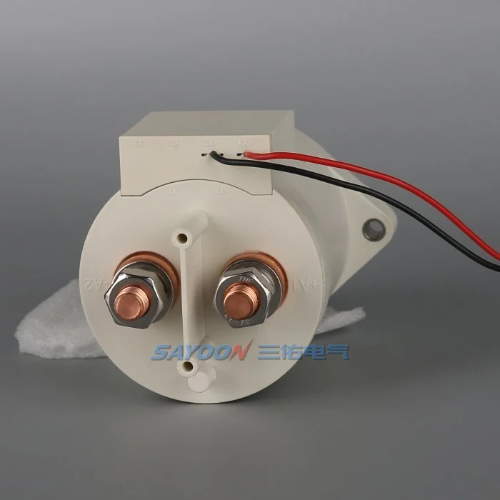
Fit Boundary: SAYOON main contactor SKUs do not automatically include precharge resistors, timers, or sequence firmware unless a specific bundle is confirmed.
Part 7. What failures occur when mains close before precharge completes?
Early main close can weld contacts, trip DC breakers, fault PCS input stages, or produce voltage dips that cascade into EMS shutdowns. Field teams often misdiagnose these as “contactor underrated” when the sequence chart never defined threshold or timeout.
Common root causes
- Threshold sense on wrong net
- Timeout too long relative to resistor heat rating
- Main driver not interlocked to precharge state
- Auxiliary feedback ignored by software debounce
- Precharge device omitted from BOM while mains specified
When sequence documentation is incomplete, send precharge sequence and bus capacitance for engineering review before repeating failed commissioning cycles.
References
- BatteryDesign.net — High Voltage System — precharge path context
- EVolve Library — HV Battery Architecture — sequenced energisation overview
- ISO 6469-3 scope (road vehicles — electrical safety) — system safety context
FAQ
Why is precharge required before closing HV battery contactors?
Precharge limits inrush current onto capacitive DC buses so main contactors close onto a partially equalised voltage rather than a near-short at the capacitor.
What is the difference between precharge and main contactors?
Precharge contactors connect a controlled inrush path through a resistor or limiter. Main contactors carry the sustained battery-to-bus connection after the threshold is met.
How long should precharge take on a BESS DC bus?
Duration depends on bus capacitance, precharge current limit, and target threshold. Document a maximum timeout on the sequence chart rather than assuming a fixed industry seconds value.
What voltage threshold confirms precharge is complete?
Teams typically define a percentage of pack or bus nominal at a specified sense node with hysteresis. Record the node name and filter time on the chart.
What happens if main contactors close before precharge finishes?
Expect high inrush current, possible protection trips, contact welding risk, and PCS faults. Sequences should interlock main drivers until threshold and health checks pass.
Who owns precharge hardware versus the main contactor?
Integrators own the sequence chart. Main contactor SKUs come from the contactor supplier; precharge resistors, limiters, and timers may be separate BOM lines unless a bundle is confirmed.
How does this differ from EV disconnect selection guides?
Selection guides size devices for voltage, current, and duty. This article documents energisation order, thresholds, and commissioning — control logic separate from ampere labels.





