HVDC contactor integration on BESS main circuits starts with a marked single-line diagram, frozen voltage and current classes, precharge and protection coordination with the BMS and PCS, and commissioning checks that prove contactor feedback before the DC bus is energised.
This checklist is for integrators and EPC teams who must hand over traceable records to owners, insurers, and grid operators. For string-level current discussions, see string-level DC contactor sizing. Start SKU comparisons at HEV Series HV DC contactors.
Contents
- Part 1. Where do HVDC contactors sit on BESS main circuits?
- Part 2. What integration inputs should be frozen before contactor placement?
- Part 3. Which electrical specification fields belong on the integration record?
- Part 4. How should contactors coordinate with BMS, fuses, and PCS protection?
- Part 5. What mechanical, thermal, and environmental checks affect integration?
- Part 6. What commissioning steps verify HVDC contactor function on site?
- Part 7. Which RFQ package helps match an HEV or SEV candidate?
Part 1. Where do HVDC contactors sit on BESS main circuits?
On many rack-to-container architectures, hvdc contactor devices appear at more than one hierarchy level. Treat each location as a separate line item on the integration record with its own voltage, current, and switching duty.
| Main-circuit location | Typical purpose | Integration note |
|---|---|---|
| Container or skid main disconnect | Isolate entire DC bus for service | Highest current class |
| PCS DC interface | Connect/disconnect converter | Coordinate with PCS precharge |
| String or rack feeder | Maintainability and fault segmentation | Lower current, higher cycle count |
| Redundant pole arrangements | Platform-dependent safety concept | Document series/parallel pole strategy |
Application guides for energy storage emphasise roles such as battery rack connection, DC bus coupling, inverter interface, and rapid isolation during insulation faults. Your UPS and energy storage applications page describes fast-switching contactors for transfer and large-scale storage contexts — use it as application background, not as a substitute for your SLD.
Articles on high-current BESS main paths help when nominal current reaches hundreds of amperes, but they do not replace HVDC class, pole placement, or protection coordination on the integration checklist.
Part 2. What integration inputs should be frozen before contactor placement?
Integrators who skip this step often discover late that the chosen hvdc contactor cannot fit the busbar pitch, lacks auxiliary feedback the EMS expects, or cannot be coordinated with the PCS fault clearing time.
Integration input checklist
| Document / input | Owner | Minimum content |
|---|---|---|
| Single-line diagram (DC portion) | Engineering | Contactor tags, fuse IDs, PCS port |
| BMS fault reaction matrix | BMS supplier | Open commands, delays, retries |
| PCS protection settings | PCS vendor | DC overcurrent, precharge, ride-through |
| Nominal and max DC bus voltage | System design | At contactor terminals |
| Continuous and peak current per tag | System design | Charge, discharge, fault study |
| Switching duty per tag | O&M concept | Cycles per day/year |
| Environmental class | Mechanical | IP, corrosion, altitude |
| Target standards list | Compliance | Owner/grid requirements |
The TPS BESS design guide lists DC protection, pre-charge, and verification planning as part of the same integration exercise — not as aftermarket additions.
Part 3. Which electrical specification fields belong on the integration record?
Copy the following table into your component schedule so procurement and commissioning teams work from one schema.
| Field | Question it answers | Typical source |
|---|---|---|
| Contact voltage class | Can contacts hold off max DC potential? | System voltage study |
| Continuous current (DC-1) | Thermal carry while closed | Mode analysis |
| Short-time overload | PCS or grid event profiles | PCS/BMS data |
| Interrupt / rupture capability | Defined fault energy at voltage | Supplier test sheet |
| Coil voltage and duty | Control power availability | BMS/PLC I/O list |
| Auxiliary contacts | EMS/BMS feedback | Controls schematic |
| Electrical life | Maintenance interval | Cycle estimate |
| Mechanical life | Actuation durability | Maintenance plan |

Manufacturer checklists such as the Weltrus BESS DC contactor guide stress voltage, current, arc suppression, certification scope, thermal performance, and BMS integration as one package. Missing any column tends to delay FAT and SAT.
Part 4. How should contactors coordinate with BMS, fuses, and PCS protection?
Contactors are expected to interrupt normal load current during controlled opens. Short-circuit energy is usually delegated to fuses, PCS semiconductor protection, or dedicated fast disconnect devices according to the coordination study. Mixing those roles without documentation is a common integration failure.
Coordination principles
- BMS commands open contactors on cell-level faults, insulation warnings, or operator estop — record delay and whether opens are under load.
- Fuses or DC breakers handle high fault energy; contactor rupture fields must be compared at the system voltage, not assumed.
- PCS may require precharge before closing to the DC bus; contactor closure interlocks should follow PCS readiness bits.
- EMS should read auxiliary feedback where available; coil voltage alone is not a position proof.
| Event class | Typical primary actor | Contactor role |
|---|---|---|
| Normal shutdown | BMS/EMS | Open after current falls |
| Maintenance isolation | Operator + interlock | Open and lockout |
| DC overcurrent | PCS or fuse | May open after threshold |
| Short-circuit | Fuse / pyro / PCS | Energy coordination, not guesswork |
For adoption background linking storage and mobility supply chains, see energy storage adoption context.
Part 5. What mechanical, thermal, and environmental checks affect integration?
Mechanical integration determines whether the contactor can be serviced, torqued, and cooled as assumed in the datasheet. Environmental class determines whether condensation, salt, or altitude derating is required.
Mechanical and environmental checklist
- Busbar orientation and creep/clearance to enclosure walls meet your HV spacing rules
- Torque spec for main terminals recorded (published examples on SAYOON HV pages include M10 mains on SEV class models)
- Coil lead length and routing compatible with harness bend radius
- Ambient range matches site survey (published SAYOON HV examples include −40 °C to +85 °C ambient on SEV400AH page)
- IP rating matches enclosure marketing (published IP68 on representative SEV SKU — confirm per model)
- Vibration class matches container transport and seismic category if applicable
Thermal planning should state whether natural convection is sufficient or forced air is required for the continuous current you assigned to each tag. Do not assume enclosure HVAC covers contactor terminal temperature rise without measurement points.
Part 6. What commissioning steps verify HVDC contactor function on site?
Commissioning proves that drawings, BMS logic, and hardware behaviour match. Adapt the steps to your FAT/SAT protocol.
| Step | Action | Pass criterion |
|---|---|---|
| 1 | Verify nameplate vs schedule | Model, coil voltage, auxiliaries match |
| 2 | Insulation / hi-pot per plan | Within owner specification |
| 3 | Auxiliary wiring continuity | Feedback changes with commanded state |
| 4 | Precharge sequence dry run | Voltage threshold met before main close |
| 5 | Controlled open/close at low current | BMS/EMS logs match measured bus |
| 6 | Interlock test | Opens on door/service interlock break |
| 7 | Thermal snapshot at rated current | Terminal rise within supplier limit after soak |
| 8 | Document as-built SLD | Redlines uploaded to O&M record |
Commissioning guides for grid-connected BESS emphasise communication handshake between BMS, PCS, and EMS before energisation. Resolve protocol mismatches in FAT, not on the owner site.
Part 7. Which RFQ package helps match an HEV or SEV candidate?
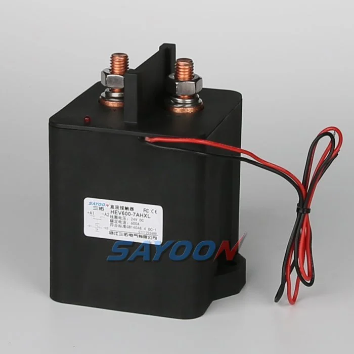
Send one ZIP or ticket containing the items below so application engineering can map current steps across HEV Series HV DC contactors and, when current fits better, SEV Series HV DC contactors.
RFQ package
| Item | Detail required |
|---|---|
| SLD PDF | Tags circled for each contactor location |
| Voltage sheet | Nominal, max charge, max regen if applicable |
| Current sheet | Continuous and peak per tag |
| Duty sheet | Cycles/day and expected service life |
| Coil specification | Voltage, suppression, economizer needs |
| Auxiliary map | NO/NC counts and sense circuit |
| Environment | IP, temperature, altitude, corrosion class |
| Certification targets | Markets and required marks |
Fit Boundary
- Suitable when main-circuit voltage and continuous current fit published SAYOON HEV/SEV classes, protection coordination is documented, and auxiliary feedback matches your EMS inputs.
- Not suitable when you require utility-scale multi-pole redundancy definitions, owner-mandated grid-code system certificates, or rupture energy proof at bus voltage without supplier validation.
- Confirm first whether each tag is container main, PCS, or rack feeder — current steps differ.
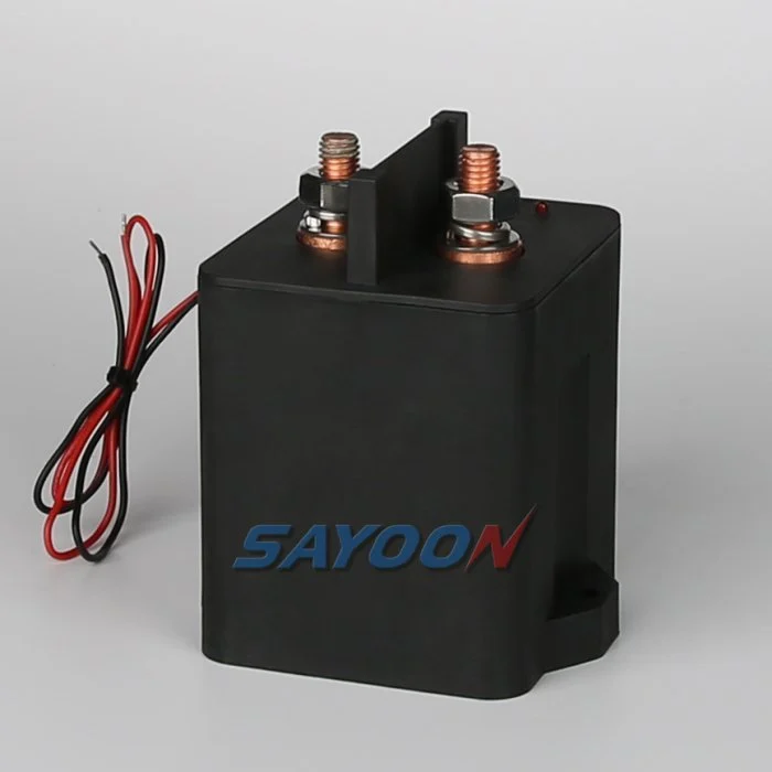
Share SLD and protection settings when you want SAYOON to propose a coil variant, auxiliary layout, and mounting bracket for your integration record.
FAQ
What does an HVDC contactor do in a battery energy storage system?
It connects or isolates DC paths under BMS/EMS command so racks, containers, or PCS interfaces can be serviced safely and faults can be segmented.
Where are DC contactors installed in a BESS main circuit?
Common tags include container main disconnect, PCS DC interface, and rack or string feeders — each needs its own record line.
How do you size a contactor for energy storage?
Match contact voltage class, continuous current, switching duty, and coordination with fuses/PCS; verify rupture fields at your bus voltage with the supplier.
Why is precharge used in BESS DC distribution?
It limits inrush into capacitive PCS or bus elements so main contactors close after voltage matching, reducing welding risk.
How do contactors coordinate with BMS and fuses in BESS?
BMS commands normal opens; fuses or PCS devices address high fault energy; the coordination study must document who acts first.
Do auxiliary contacts replace BMS voltage sensing?
No. Auxiliaries prove contactor position; pack voltage and current validation remain separate measurement functions.
When should teams choose HEV vs SEV series?
Compare published current steps, coil options, and mounting data against each tag on your schedule; application engineering can map variants after RFQ review.
References
- Weltrus — DC Contactors for Energy Storage Systems — BESS checklist and BMS coordination framing
- TPS — Battery Energy Storage System Design Guide — Integration and verification planning
- MiRelay — HV DC Contactors in Energy Storage — Application roles on main circuits
- IEC 62933-2-1 — Grid-connected energy storage systems — Grid-connected ESS safety family (context)





