A latching contactor beats a standard electrically held DC contactor on hold power when the path stays closed for long intervals and the control system can issue set/reset pulses — because magnetic holding designs hold state after a pulse with published keep power of 0 W, while standard coils continue to draw coil watts for the entire closed duty.
This comparison is for OEM power engineers and panel builders who already know contact voltage and current class, and now need to decide whether coil standby energy justifies a magnetic holding architecture. Start from the magnetic holding DC contactors pillar for the CZW-K / CZWH-K family, then use the tables below to separate coil architecture from contact ratings before RFQ.
Part 1. When does a latching contactor beat a standard DC contactor on hold power?
A latching contactor in DC OEM searches usually means a magnetic holding or bi-stable device that changes state with a short coil pulse and then holds with little or no continuous coil power. A standard electrically held DC contactor keeps the coil energized for the entire closed interval. The hold-power advantage appears when closed duty lasts minutes to hours — UPS transfer paths, telecom distribution, charging-pile branches, and other long-engage circuits — not when the contactor jogs every few seconds.
Use latching when three conditions are true at once: (1) closed duty is long enough that continuous coil watts matter, (2) the controller can command set and reset pulses with documented polarity and width, and (3) the safety concept tolerates state retention after control-power loss, or adds an independent isolation device. If any condition fails, keep a standard coil architecture.
| Decision signal | Favors latching / magnetic holding | Favors standard electrically held |
|---|---|---|
| Closed-duty duration | Hours or continuous engage | Frequent open/close cycles |
| Coil energy budget | Battery, solar, or low-standby panels | Control power is plentiful |
| Fail-safe expectation | State memory acceptable, or separate isolator exists | Must open when coil power is lost |
| Driver hardware | Pulse / bi-stable driver available | Simple on/off coil driver only |
For industrial-truck voltage context that often sits beside these coil decisions, see 48 V DC contactor selection for industrial trucks.
The latching vs non-latching selection framing at VIOX is useful for pulse-versus-continuous vocabulary — it does not replace your contactor datasheet RFQ table.
Part 2. How do coil architectures differ after the contacts close?
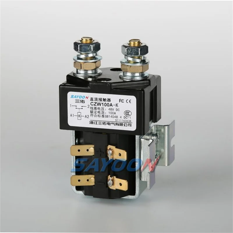
After close, a standard CZW-class coil continues to consume published coil power for as long as the path stays closed. Published CZW100A coil power is 8–13 W. A magnetic holding SKU such as CZW100A-K publishes K Start: 10–15 W, Keep: 0 W, with pulse duration 200 ms ≤ t ≤ 1 s. The architectural difference is therefore measurable on the datasheet lines — not inferred from marketing labels alone.
| Coil field to read | Standard CZW100A (published) | Magnetic holding CZW100A-K (published) |
|---|---|---|
| Coil power while held | 8–13 W (coil power line) | Keep: 0 W |
| Energy window for state change | Continuous energize | Pulse 200 ms–1 s |
| Start / inrush class | Included in coil power band | K Start: 10–15 W |
| Driver implication | Maintain coil voltage for closed duty | Set/reset pulse with polarity control |
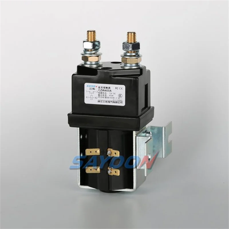
Higher magnetic holding classes keep the same Keep: 0 pattern on published tables: CZW200A-K lists K Start: 15–20, Keep: 0; CZW400A-K lists K Start: 18–30, Keep: 0. Always re-read the SKU page before freezing a BOM line.
Coil voltage stability still matters on either architecture — see 24 V contactor coil stability notes when your control net sits near brownout corners.
Part 3. Which control-logic and fail-safe checks change with magnetic holding?
Magnetic holding changes the control story more than the bus-bar story. Your PLC or BMS must generate a set pulse to close and a reset pulse to open. Reusing a continuous on/off coil output without a pulse former is a common integration failure. Document pulse width, polarity, and maximum operating frequency against the published SKU limits — CZW100A-K lists operating frequency ≤6 times per minute (square wave) on the product page.
Control and safety checklist
- Confirm the driver can enforce the published pulse window (for CZW100A-K: 200 ms–1 s).
- Record set versus reset polarity on the harness drawing.
- Decide whether control-power loss must force the main path open — if yes, latching alone is not your isolator.
- Map optional auxiliary contacts to PLC inputs when position feedback is required.
- Cap command rate within the published operating-frequency limit.
| Control RFQ field | Why it blocks release if omitted | Supplier should return |
|---|---|---|
| Pulse width min/max | Driver firmware mismatch | Published pulse duration |
| Coil rated voltage | Control net selection | Coil voltage options on SKU |
| Aux contact rating | Sense-circuit overcurrent | Optional aux load rating |
| Behavior on control loss | Safety concept gap | Application note / engineering reply |
| Max ops per minute | Premature wear | Published operating frequency |
Part 4. How should buyers compare contact ratings separately from coil savings?
Hold-power savings never relax contact voltage, continuous current, or rupture requirements. Compare contact lines on the same matrix for both architectures before declaring a winner. Published CZW100A-K contact voltage is ≤80 V with 100 A DC-1 on a 48 V circuit example; CZW100A publishes the same contact voltage class and 100 A DC-1 load current line. If your bus exceeds those published bounds, move amp class or series — do not “stretch” a latching SKU because Keep watts look attractive.
| Contact field | What to freeze on RFQ | Common error |
|---|---|---|
| Contact voltage (DC) | Maximum working + headroom process | Treating ≤80 V as universal |
| Rated load current | Continuous current at duty | Using peak inrush as continuous |
| Typical fault rupture | Fault study value and duration | Ignoring ms duration on the table |
| Terminal / torque | Bus hardware plan | Discovering M8/M10 mismatch at build |
| IP / environment | Enclosure class | Assuming sealed HV behavior on IP40 LV parts |
Standard CZW series DC contactors remain the right shortlist when your duty is frequent switching with electrically held fail-safe open behavior — even if coil watts are higher.
Part 5. Which SAYOON SKU classes illustrate latching vs standard choices?
Use one standard and one magnetic holding candidate at the same amp class when the RFQ is really about coil architecture. For 100 A class illustration, pair CZW100A with CZW100A-K. For higher continuous current under magnetic holding, step to CZW200A-K or CZW400A-K using published load-current lines (200 A and 400 A DC-1 @48 V respectively).
| Program need | Starting comparison pair | First published fields to read |
|---|---|---|
| 100 A long closed duty, low standby | CZW100A vs CZW100A-K | Coil power / Keep; pulse duration |
| 200 A magnetic holding branch | CZW200A-K | Load current 200 A; Keep: 0 |
| 400 A magnetic holding branch | CZW400A-K | Load current 400 A; K Start band |
| Frequent motor jog with open-on-loss | Standard CZW class | Coil power; pull-in / drop-out timing |
Browse the full magnetic holding catalog on the series pillar before locking amp class. CZWH-*K SKUs address higher current magnetic holding envelopes — confirm each published table independently.
Part 6. What RFQ matrix validates a hold-power shortlist?
Copy the matrix below into the RFQ packet. Mark each line Pass / Review / Fail for one latching candidate and one standard candidate. Escalate when safety concept or pulse driver capability is unclear.
| RFQ line | Latching / -K candidate | Standard candidate | Owner |
|---|---|---|---|
| Max contact voltage | Power engineer | ||
| Continuous current & duty | Thermal lead | ||
| Coil architecture (pulse vs continuous) | Controls | ||
| Keep / coil watts while closed | Controls | ||
| Pulse width & polarity | Firmware | ||
| Open-on-control-loss requirement | Safety | ||
| Aux feedback needed? | PLC / BMS | ||
| Outline & mounting bracket | Mechanical | ||
| Cert marks required on label | Compliance |
Product recommendation: start hold-power comparisons with the CZW100A-K magnetic holding DC contactor when your published need fits ≤80 V contact voltage and 100 A DC-1 @48 V. Step to CZW200A-K / CZW400A-K when continuous current exceeds that class. Prefer the CZW100A normally open DC contactor when the safety concept requires electrically held open-on-coil-loss behavior.
Fit Boundary: Not suitable when the controller cannot issue set/reset pulses, when automatic open on control-power loss is mandatory without a separate isolator, or when contact ratings exceed the published SKU table.
To confirm a shortlist, send coil driver and duty-cycle notes with the completed matrix.
Part 7. What mistakes waste the latching advantage on OEM programs?
- Choosing -K only for marketing “zero power” language without verifying the Keep line on the exact SKU page.
- Driving a magnetic holding coil from a continuous on/off output with no pulse timing.
- Ignoring open-on-control-loss requirements until the safety review.
- Stretching contact voltage or current because coil savings look large.
- Exceeding published operating frequency on high-cycle paths.
- Mixing amp classes across poles without a per-pole RFQ row.
- Skipping auxiliary feedback when the PLC needs positive confirmation of state.
References
- Latching vs Non-Latching Relay Selection Guide — VIOX
- IEC — International Electrotechnical Commission
FAQs
What is a latching contactor in DC systems?
A latching (magnetic holding) DC contactor changes contact state with a short coil pulse and then holds that state with little or no continuous coil power. SAYOON publishes this architecture on CZW-K / CZWH-K magnetic holding SKUs.
Does latching always mean zero hold power?
Treat zero hold power as a published Keep field, not a universal law. CZW100A-K, CZW200A-K, and CZW400A-K list Keep: 0 on their product tables — re-read any other SKU before claiming the same.
When should buyers keep a standard electrically held contactor?
Keep a standard coil when switching is frequent, when the safety concept requires opening on control-power loss, or when the controller cannot supply set/reset pulses. Standard CZW series SKUs fit that pattern.
What pulse duration does CZW100A-K publish?
The CZW100A-K product page lists pulse duration 200 ms ≤ t ≤ 1 s. Design the driver inside that window unless engineering confirms a special order.
Can a standard coil driver run a -K magnetic holding model?
Usually not without modification. Magnetic holding needs controlled set/reset pulses and polarity management; a continuous energize output can overheat the coil or fail to reset the latch.
Does loss of control power open a latched contactor?
Not by default. Latching devices are designed to retain state after the pulse ends. If open-on-loss is required, specify an electrically held contactor or add a separate isolation device and document the safety concept.
Which series page should start a magnetic holding RFQ?
Start at the magnetic holding DC contactors series page, then open the amp-class SKU tables for Keep power, pulse duration, and contact ratings.





