Contactor coil power consumption is not one universal number. A conventional DC coil may draw its highest power throughout the energized period, while an economized coil uses a stronger pull-in level and a lower hold level. Size the driver from the approved pull-in current, hold current, voltage tolerance, duration, switching frequency, temperature, suppression method, and cable drop for the exact coil option. This guide provides an engineering review method, not a universal pass/fail value.
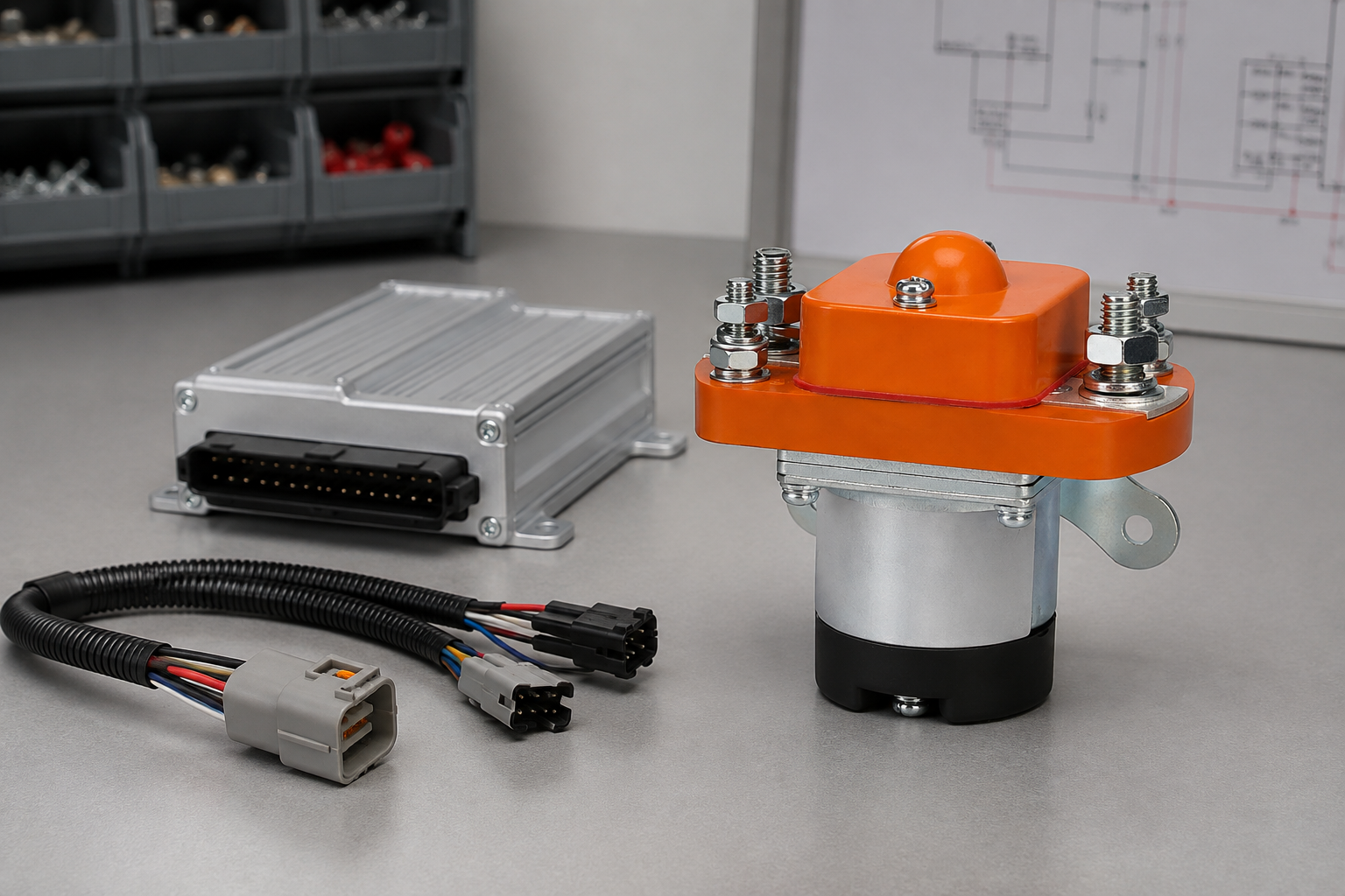
Key evidence to collect
| Review item | Evidence to collect | Why it matters |
|---|---|---|
| Pull-in demand | Peak coil current at minimum and maximum supply conditions | Checks driver current limit and available pickup margin |
| Hold demand | Stabilized current after any economizer transition | Sets continuous driver and thermal load |
| Energy per operation | Current and voltage waveform integrated over time | Useful for battery budget and repeated cycling |
| Release behavior | Current-decay waveform after command off | Suppression can change dropout time |
| Worst-case wiring | Voltage measured at coil terminals | Includes harness and controller losses |
Separate pull-in power from hold power
The open magnetic circuit has a large air gap. Closing it requires enough ampere-turns to overcome spring force, friction, tolerances, and supply variation. After the armature seats, the magnetic reluctance is lower, so some designs can reduce coil current. An external or internal economizer may make that transition, but the controller must not assume one exists. The approved ordering code and wiring diagram must identify the coil design.
Use a waveform, not a single meter reading
A handheld meter may average the short pull-in event and hide a current limit, voltage collapse, PWM hold strategy, or intermittent reset. Capture voltage directly across the coil and current in the same time record. Mark command-on, first movement, full closure, economizer transition, steady hold, command-off, and release. Repeat cold and hot because copper resistance changes with temperature and the mechanism may also behave differently.
Translate coil demand into a driver specification
The driver review should cover continuous current, transient current, safe operating area, output voltage, voltage-drop budget, protection behavior, diagnostic leakage, off-state voltage, suppression energy, and fault response. A driver that survives the steady hold current can still current-limit during pickup. Conversely, a driver sized only for the peak can overheat when many contactors remain energized together.
Account for system-level energy and heat
Coil demand contributes to enclosure heat and, in vehicles or battery systems, standby energy. Calculate from measured voltage and current over the actual duty profile, not only nominal voltage divided by nominal resistance. Include the controller, economizer, suppression network, and harness if the purpose is a system power budget. The product value and the complete installed-circuit value are different questions.
Turn the result into an engineering decision
Review the evidence with design, quality, safety, controls, and supplier representatives when the result affects system release. State what was measured, what was inferred, and what remains unknown. A pass should identify the exact requirement and applicable condition. A failure should preserve the original evidence, describe immediate containment, and assign the next confirmation step. If the result is inconclusive, improve the method, obtain missing product data, or repeat the test under controlled conditions. After corrective work, repeat the baseline measurements and the operating sequence that exposed the issue. Check that the correction did not create a new problem in release time, thermal behavior, auxiliary feedback, insulation, protection coordination, or service access. Record the approved configuration so production and field teams can reproduce it. This closes the loop between a useful test result and a reliable contactor installation.
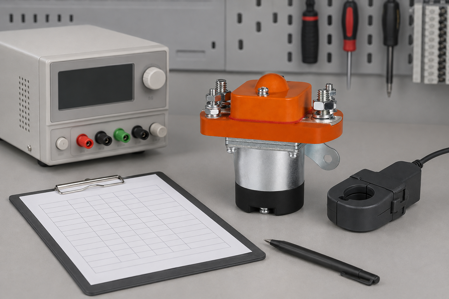
Build the test around a written question
Begin by writing the decision the evidence must support. A troubleshooting test asks whether an installed circuit explains a symptom. A production test asks whether a repeatable assembly meets an approved limit. A design-validation test asks whether the device and system remain acceptable across the operating envelope. Mixing those purposes produces readings that look precise but cannot support a release decision.
Define the exact ordering code, coil option, contact arrangement, terminal map, revision, and condition of the sample. Record whether the unit is new, conditioned, field-returned, or previously faulted. Identify the main-circuit voltage and current range, control supply, load type, duty, temperature, mounting, conductor interfaces, suppression, protection, and software state. These details prevent a result from one setup being applied to a materially different installation.
Use a controlled evidence sequence
- Review documents. Obtain the approved schematic, product drawing, data sheet, test procedure, safety assessment, and acceptance criteria. Resolve contradictions before connecting equipment.
- Identify energy. Trace every normal, backup, regenerative, capacitive, and externally supplied source. Include stored mechanical and electrical energy.
- Inspect first. Photograph the device and terminals. Check mounting, conductors, fasteners, contamination, heat evidence, coil wiring, auxiliary wiring, and unauthorized changes.
- Verify instruments. Confirm rating, isolation, calibration status, leads, probes, bandwidth, sampling, zeroing, and the effect the instrument can have on the circuit.
- Measure at the device. Sense coil and main-circuit quantities at the defined contactor boundaries so harness and joint effects are visible or deliberately excluded.
- Exercise the real sequence. Include precharge, interlocks, normal start and stop, emergency behavior, restart restrictions, and representative thermal conditions.
- Repeat and compare. Collect enough cycles to see variation. Compare only with written limits that apply to the exact product and conditions.
- Retain the record. Save raw waveforms, units, settings, photos, environmental conditions, reviewers, deviations, and disposition.
Safety and authority: Treat every power circuit as hazardous until an authorized person has isolated all sources, applied the site’s lockout procedure, verified absence of voltage with a suitable instrument, and controlled stored energy. The OSHA control-of-hazardous-energy rule and OSHA electrical work-practice requirements provide a general framework. Product selection and test acceptance must use the exact manufacturer data and the applicable project standards. IEC 60947-4-1 is a relevant standards reference for electromechanical contactors and motor-starters; use the edition adopted by the project.
Measurement quality and uncertainty
Instrument resolution is only one part of uncertainty. Probe position, contact pressure, lead resistance, bandwidth, sampling rate, common-mode voltage, electrical noise, threshold choice, temperature, current stability, timing reference, and operator technique can all change a result. Record enough information for another engineer to reproduce the setup. When a reading is close to a limit, repeat it with a reviewed method instead of rounding toward a desired conclusion.
Separate measured facts from interpretations. “Coil voltage fell during pickup” is an observation. “The contactor is defective” is a conclusion that may not follow if the controller current-limited or the cable drop was excessive. Change one variable at a time where practical. Compare terminal-side and source-side measurements, and preserve the original condition before cleaning, tightening, or replacing parts.
Common diagnostic traps
Do not approve a contactor from a single room-temperature bench operation with short leads and no representative load. Do not use an auxiliary contact as automatic proof of the main-current state. Do not copy a voltage, resistance, time, or temperature limit from another model. Do not combine the most favorable values from separate catalogue tables unless the manufacturer confirms that they apply simultaneously. Do not adjust controller delays to hide unstable hardware before the cause is known.
A replacement can fit mechanically and still be unsuitable. Review coil voltage tolerance, pull-in and hold behavior, internal electronics, suppression compatibility, main-contact voltage, make and break duty, current direction, auxiliary contacts, terminals, mounting, thermal conditions, environment, service life, and fault coordination. The selected device, driver, load, protection, installation, and operating sequence form one system.
Product and RFQ connection
The MZJ-100A Normally Open DC Contactor is a relevant Sayoon product-family example for this topic, not automatic approval for every condition in this article. Use the exact product drawing and ordering code. For a broader review, see the DC contactor selection guide, the safe DC contactor test workflow, and the wiring and comparison hub.
An effective RFQ describes maximum and minimum voltage, normal and abnormal current waveforms, load characteristics, switching direction, precharge, protection, coil supply and driver, suppression, auxiliary logic, duty, ambient range, enclosure, mounting, conductor interface, timing, life target, required tests, and documentation. Ask the supplier to confirm which requirements are covered by published data and which need project-specific validation.
What the final record should contain
Keep the full device code and serial or lot reference where available; drawing and software revisions; date; operator; reviewer; instrument models and calibration status; terminal map; sensor locations; raw data; calculated values; units; environmental conditions; current and voltage waveforms; operating sequence; deviations; photographs; acceptance criteria; and final disposition. If the sample differs from production intent, list every difference. This record lets purchasing, design, quality, commissioning, and service teams reach the same conclusion without relying on memory.
Educational video
What Is a Contactor and How Does It Work? by Electrician U provides a visual introduction to contactor operation. It is background education; the written product data and approved procedure remain controlling.
Watch the educational video on YouTube.
Frequently asked questions
Can I calculate coil power from resistance alone?
Only as a rough DC steady-state check when the coil is a simple resistor at a known temperature. It does not describe pull-in dynamics, economizers, PWM control, cable drop, or suppression.
Why is pull-in current higher than hold current?
Some designs deliberately apply more magnetic force to close the air gap, then reduce current after the armature seats.
Where should voltage be measured?
Measure at the coil terminals while the real driver and harness are operating.
Does a diode reduce coil power?
A flyback diode mainly changes turn-off current decay. It is not a substitute for measuring pull-in and hold demand.
What should be sent with an RFQ?
Send coil-voltage range, driver type, current limits, duty, ambient conditions, suppression, timing requirements, and the desired measured evidence.
Final review
Confirm the exact contactor, circuit boundary, energy state, operating condition, measurement method, acceptance source, uncertainty, repeatability, and reviewer before releasing a design or returning equipment to service. If a required limit is absent, request written product-specific evidence rather than inventing a threshold.





