For teams researching dc contactor mounting orientation, the practical answer is this: DC contactor mounting orientation can affect armature motion, spring forces, arc movement, cooling, drainage, terminal loading, and vibration response. Use only orientations approved for the exact model. If an alternative orientation is required, obtain written evidence or validate timing, pickup and dropout, temperature rise, interruption, vibration, and environmental behavior in that position. This guide explains a traceable selection and verification process; it does not create a universal rating or replace project-specific safety approval.
Start with the installed system, not a catalogue number
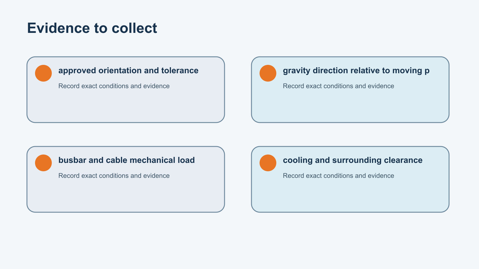
The contactor is one part of a circuit that includes the source, protection, conductors, load, controller, coil driver, suppression, enclosure, and operating sequence. Write down the normal operating state, every transition, and credible abnormal states before comparing products. For dc contactor mounting orientation, the most important inputs are approved orientation and tolerance, gravity direction relative to moving parts, busbar and cable mechanical load. A catalogue maximum rarely means that all maximum values can occur together. Footnotes, conductor sizes, mounting conditions, temperature, and test definitions determine what the rating actually supports.
Separate facts from assumptions. A measured current waveform is evidence; an estimated current based on nameplate power is an assumption. A supplier statement tied to a full part number and test report is stronger than a family brochure. Keep the full ordering code, drawing revision, test condition, and responsible reviewer in the selection record. This prevents later purchasing substitutions from silently changing the electrical or environmental behavior.
Define the operating envelope
Use minimum, nominal, and maximum values rather than one typical point. Include startup, shutdown, precharge, regeneration, emergency isolation, restart, maintenance, and fault recovery. Temperature, supply tolerance, wiring loss, contamination, altitude, vibration, and aging can shift the same contactor into a different condition. The operating envelope should show how often each event occurs and whether the device is expected to make, carry, or break current during it.
- approved orientation and tolerance
- gravity direction relative to moving parts
- busbar and cable mechanical load
- cooling and surrounding clearance
- water drainage and contaminant collection
- vehicle or machine acceleration axes
Record which value is measured, calculated, simulated, or supplied. Include tolerances and measurement uncertainty. If a required input is missing, mark the selection open instead of inserting a convenient value. This simple discipline is especially important for high-voltage and high-current DC systems, where arc behavior and thermal stress can change sharply with conditions.
Build a traceable selection table
| Review area | Evidence to collect | Decision supported |
|---|---|---|
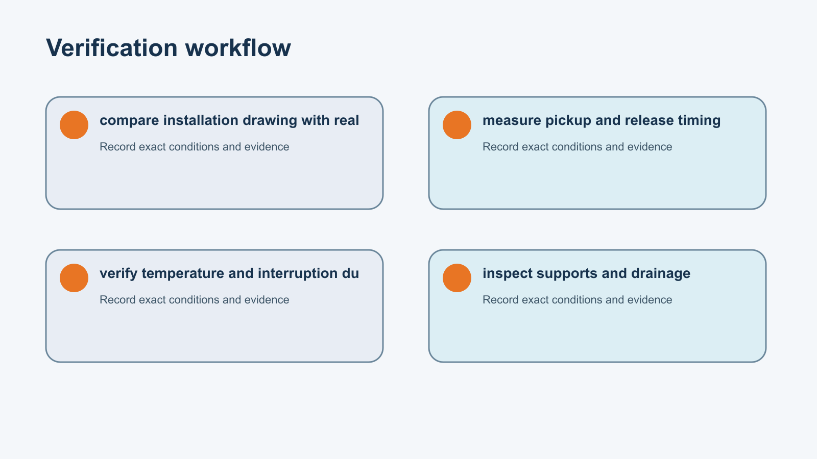
| approved orientation and tolerance | Drawing, waveform, measurement, or written supplier evidence for the exact configuration | compare installation drawing with reality |
| gravity direction relative to moving parts | Drawing, waveform, measurement, or written supplier evidence for the exact configuration | measure pickup and release timing |
| busbar and cable mechanical load | Drawing, waveform, measurement, or written supplier evidence for the exact configuration | verify temperature and interruption duty |
| cooling and surrounding clearance | Drawing, waveform, measurement, or written supplier evidence for the exact configuration | inspect supports and drainage |
| water drainage and contaminant collection | Drawing, waveform, measurement, or written supplier evidence for the exact configuration | compare installation drawing with reality |
| vehicle or machine acceleration axes | Drawing, waveform, measurement, or written supplier evidence for the exact configuration | measure pickup and release timing |
The table is intentionally qualitative because universal limits would be misleading. Fill it with product-specific values from approved documents. Where a standard supplies a method, record the standard edition and the project’s chosen assumptions. Where the manufacturer supplies a curve, preserve the curve, axes, notes, and interpolation method. Never copy a limit from a different contactor merely because its case looks similar.
Review the main failure paths
The review should ask how the design can fail, how the controller will detect the failure, and what state the system reaches afterward. For this topic, important traps include assuming symmetric housing means any orientation; cantilevering heavy cables from terminals; creating a water trap; changing arc behavior in a polarized design; invalidating vibration evidence. Consider contact welding, failure to close, unexpected opening, excessive heating, insulation breakdown, misleading auxiliary feedback, damaged terminals, and a protective device that does not clear the fault as assumed.
- assuming symmetric housing means any orientation
- cantilevering heavy cables from terminals
- creating a water trap
- changing arc behavior in a polarized design
- invalidating vibration evidence
Do not solve an electrical weakness only in software. Longer delays can hide slow pickup; aggressive filtering can hide bounce; repeated automatic retries can add thermal and contact stress. Software safeguards are valuable when they are based on verified hardware behavior and include timeouts, plausibility checks, and a safe abort state.
Plan the verification sequence
Begin with document review and a de-energized inspection. Confirm the part number, terminal map, polarity, mounting, conductor interfaces, fasteners, coil option, auxiliary contacts, and visible damage. Then verify the instruments, isolation, bandwidth, sensor ranges, sampling, and calibration. Measure at the contactor terminals when possible so cable and controller effects are visible rather than assumed.
- Freeze the exact hardware and software configuration.
- Identify every energy source and stored-energy element.
- Inspect mounting, terminals, insulation, and conductor support.
- Capture coil voltage, coil current, main voltage, load current, and feedback on a common time base.
- Exercise representative normal transitions before corner and fault cases.
- Repeat enough cycles to understand variation, not only the best trace.
- Compare results with written acceptance criteria for the exact configuration.
- Retain raw data, photographs, calculations, deviations, and final disposition.
The key verification actions for dc contactor mounting orientation are compare installation drawing with reality; measure pickup and release timing; verify temperature and interruption duty; inspect supports and drainage. High-energy tests belong in an approved facility with appropriate barriers, instrumentation, protection, and qualified personnel.
Interpret measurements without overclaiming
One measurement can combine several effects. Voltage drop may include the internal contact path, terminal interfaces, lugs, and busbars. Temperature may reflect load current, coil power, enclosure airflow, nearby heat, and sensor placement. Timing may include controller delay, cable drop, magnetic motion, contact bounce, and current extinction. Define the measurement boundary and keep it constant when comparing results.
When a result is close to a limit, repeat it and quantify uncertainty. Check probe location, sensor zero, bandwidth, current stability, temperature, tightening condition, and the sample’s history. Do not round toward a desired pass. If a result differs from simulation, investigate the model inputs and physical setup before deciding that either one is wrong.
Connect the topic to product selection
The MZJ-200A Normally Open DC Contactor is a relevant Sayoon product-family example, not automatic approval for this application. Review the exact ordering code and current drawing. Use the broader DC contactor selection guide to organize the main-circuit and coil requirements. The DC contactor test guide explains evidence boundaries, while voltage-drop testing and opening and closing time measurement provide complementary checks without competing with this article’s search intent.
For an RFQ, send the electrical envelope, load description, current direction, switching sequence, coil supply and driver, suppression, protection, duty, environment, mounting, conductor interface, timing, life target, standards, required documents, and validation plan. Ask the supplier to distinguish published ratings from project-specific evidence. If a proposed alternative changes any of those items, require a documented review before approval.
Common mistakes to avoid
Do not select by current, voltage, housing size, or price alone. Do not treat a conformity mark as proof that the device meets a particular application duty. Do not assume a sealed housing protects external terminals. Do not reuse an acceptance limit from a different part number. Do not let a drawing revision, coil option, or terminal material change without review. Finally, do not publish a precise number when the test condition and source are missing.
A robust decision states the boundary clearly: the selected contactor, approved driver, protection, conductor system, mounting, environment, and control sequence form one validated configuration. Production instructions and incoming inspection should preserve that configuration. Field service instructions should define what can be checked, what requires replacement, and what evidence must accompany a warranty return.
Authoritative references and safe-use boundary
This article uses public safety and engineering references as boundaries rather than as substitute product approvals. OSHA’s electrical standards resources explain why hazardous electrical work requires controlled procedures and qualified personnel. NIST’s SI electric-current guidance supports consistent voltage, current, and resistance records. IEC’s electrical safety overview provides context for standards-based design, while the exact applicable standard, edition, manufacturer data, and project safety assessment remain controlling.
Educational video
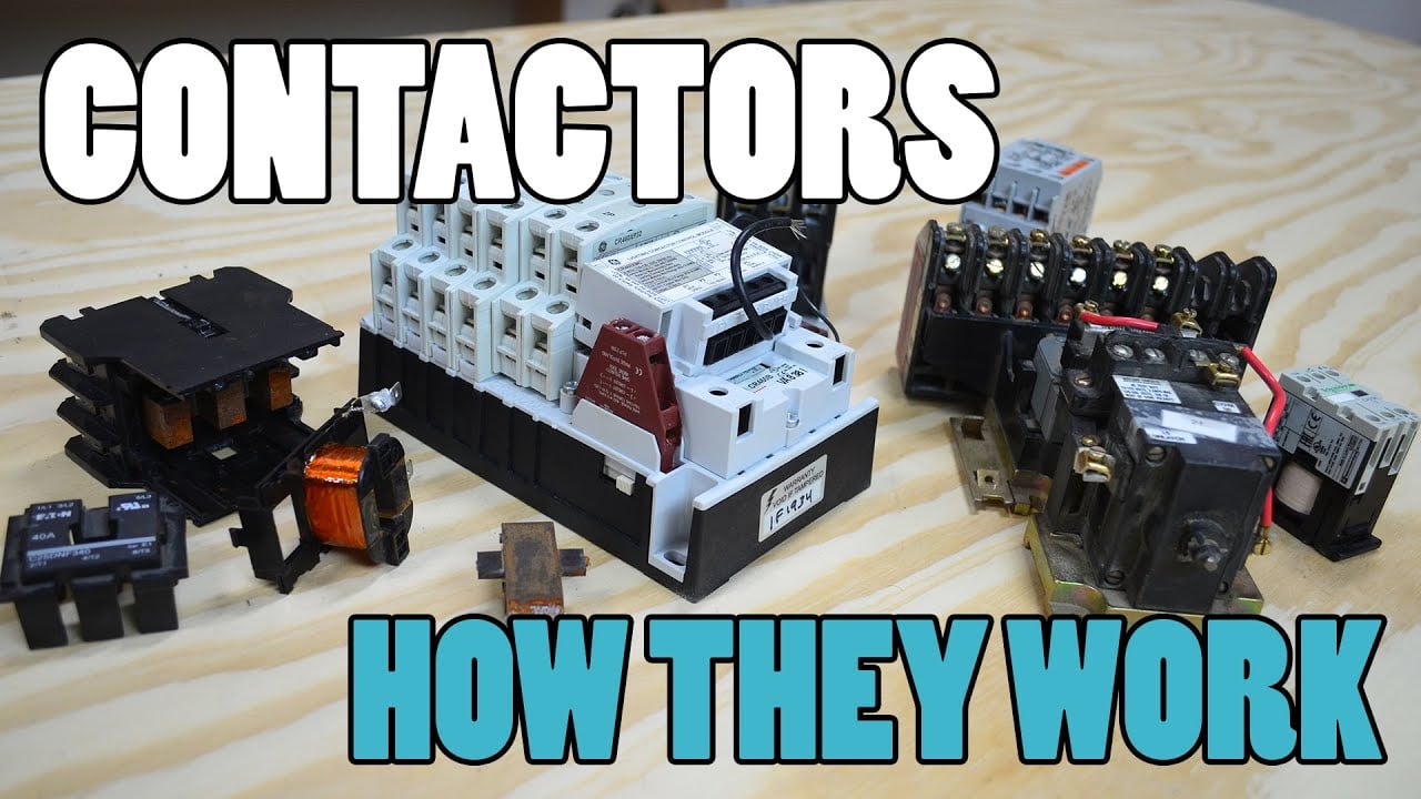
What Is a Contactor and How Does It Work? by Electrician U is included as a visual introduction to contactor operation. It does not replace the exact product drawing, application study, or approved test procedure.
Open the educational video on YouTube.
Frequently asked questions
What is the first input to confirm for dc contactor mounting orientation?
Start with approved orientation and tolerance. Record its range, source, tolerance, and operating state before comparing contactors.
Can one catalogue rating approve the application?
No. Ratings depend on stated test conditions and often cannot be combined. Use the complete product code, notes, curves, and project conditions.
Should testing use a universal pass value?
No. Use the exact manufacturer or project criterion and record the measurement boundary, instruments, environment, and uncertainty.
What belongs in the supplier enquiry?
Include approved orientation and tolerance, gravity direction relative to moving parts, busbar and cable mechanical load, cooling and surrounding clearance, plus the operating sequence, protection, environment, mounting, life target, and required evidence.
How should a failed or unclear result be handled?
Preserve the original data, place the system in a safe state, verify the method, obtain missing product evidence, and repeat only under an approved plan.
Final review
Approve the design only when the exact product, application limits, drawings, protection, conductors, mounting, environment, control sequence, acceptance criteria, and verification evidence agree. Record open assumptions and resolve them before production or field release. Recheck the decision whenever the contactor code, supplier revision, driver, fuse, busbar, cable, enclosure, software timing, or operating duty changes.





