Quick answer: Start at the controller and work toward the coil with a current-limited, isolated measurement plan. Check the low-voltage supply under load, command polarity, driver diagnostics, coil current waveform, pull-in and hold phases, release time, auxiliary transition, and bus-voltage response. Never force a coil or bridge a protection device on an energized high-voltage pack.
EV contactor coil driver diagnostics should prove the complete control path: command, supply, driver output, coil current, suppression, mechanical movement, auxiliary feedback, and the resulting high-voltage state. A missing click is only a symptom. The driver may be protecting against a short, the coil may be under-voltage, or the contactor may have moved while the feedback circuit failed.
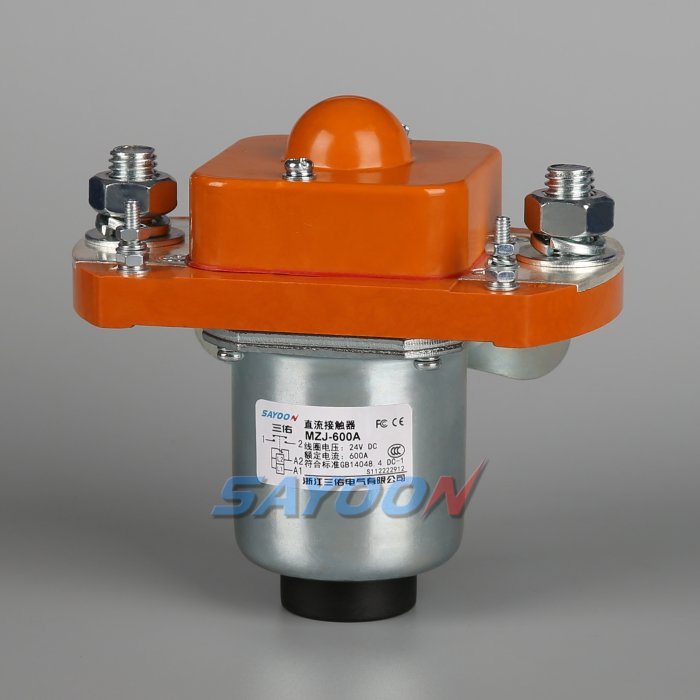
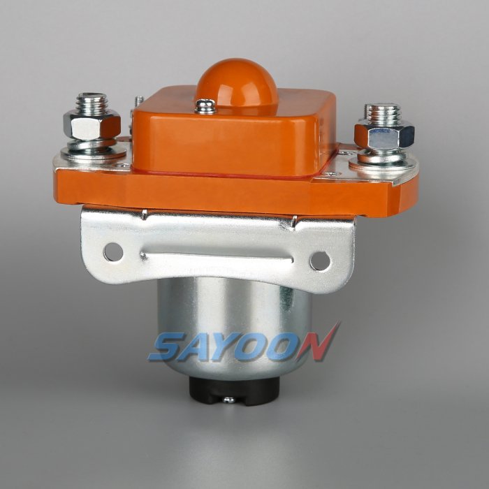
At-a-glance design map
| Element | What it does | Selection or diagnostic focus |
|---|---|---|
| Supply and ground | Measure driver supply at the connector during command | Finds brownout, ground lift and harness loss |
| Driver output | Verify high-side/low-side state and protection flags | Finds short/open-load and polarity faults |
| Coil waveform | Capture current and voltage from pull-in to hold | Finds wrong suppression, PWM or coil option |
| Mechanism and bus | Check auxiliary feedback and load-side voltage | Separates electrical command from contactor movement |
Product reference and scope
The MZJ-600A normally-open DC contactor shown in this article is a real Sayoon product reference. See the MZJ-600A normally-open DC contactor product page and the high-voltage DC contactor range for the family context. The image does not replace a model-specific drawing review; voltage, coil, current, insulation, duty, and mounting must be confirmed for the application.
Define the diagnostic boundary
The coil-driver circuit starts at a controller output and ends at the contactor coil terminals, but the diagnostic must continue to the mechanism and main bus. A driver can report “on” while a broken wire leaves the coil open. A coil can draw current while the armature fails to pull in because of low voltage, contamination, or mechanical damage. A healthy auxiliary transition can still coexist with a welded main contact.
Write each expected state in a table: command, supply, output, current, auxiliary, pack voltage, and fault flag. This lets the technician identify which layer failed instead of replacing a contactor when the real problem is a connector or software interlock.
Measure supply under real load
Measure the driver supply at the driver and at the coil connector during pull-in, not only with a multimeter at rest. Long harnesses, relays, fuses, and low-voltage battery sag can remove the pull-in margin. Check ground return voltage and connector pin fit. Record cold start, wake-up, and repeated-cycle values because a marginal supply often fails only after other loads turn on.
Do not assume the nominal coil voltage is the voltage that reaches the winding. The MZJ-600A image is a product reference; the actual coil option may be 12, 24, or another approved value. Confirm the ordering code and drawing before interpreting a current trace.
Interpret pull-in and hold current
Many contactor coils have a high pull-in demand followed by lower hold power, either through an economizer, PWM, dual winding, or integrated electronics. The current should rise and settle within the manufacturer’s expected range. A low current can indicate an open winding, high resistance, wrong PWM duty, or voltage loss. An excessive current can indicate the wrong coil, a failed economizer, or a driver that is stuck fully on.
Capture coil voltage and current on the same time base. The shape and timing matter: a slow ramp may be a supply problem, a sharp cutoff may be active suppression, and a long tail may explain delayed release. Compare the trace with an approved known-good sample.
Suppression changes release behavior
A diode, TVS, active clamp, or PWM economizer changes the turn-off voltage and the time for current to decay. Slower decay can lengthen contactor opening time; excessive voltage can damage the driver or create EMC problems. Use the suppression specified for the exact coil and driver, and check polarity before energizing. Do not add a universal diode to a circuit that already contains an internal clamp.
If the controller uses open-load or short-circuit diagnostics, the suppression network can change what the driver sees. Validate diagnostic thresholds with production harnesses, temperature, and the contactor’s connector resistance.
Separate driver, coil and mechanism faults
If the driver output is absent and its fault flag is set, diagnose supply, interlock, short protection, and software permission first. If output is present but coil current is absent, check the harness, connector, winding, and polarity. If current is correct but auxiliary feedback does not change, inspect mechanical movement and the feedback circuit. If feedback changes but the load bus does not follow, investigate the main contacts, fuse, precharge path, or measurement.
This order prevents repeated high-voltage commands during a low-voltage fault. Keep the main contactor open and the pack isolated until the coil path is understood.
Use HVIL and bus voltage as corroboration
A valid HVIL signal only permits a command; it does not prove that the coil was energized or that the main contacts closed. Combine HVIL, command, coil current, auxiliary transition, pack voltage, and load-side voltage in the fault record. A stuck-open fault commonly shows a valid interlock and command but no expected load-side rise. A welded fault can show the inverse during opening.
The related HVIL control guide explains how these signals should be separated. Keep a latched first-fault record so a later reset does not erase the evidence needed to find a marginal driver.
Commissioning and field checklist
With high voltage isolated, identify the coil pins and verify resistance against the approved range. Check the driver supply and ground under a safe test load, then connect the contactor and capture pull-in, hold, and release. Exercise the auxiliary contact with debounce and timing. Only after the low-voltage path passes should an authorized technician perform a controlled precharge and bus-voltage check.
Record instrument bandwidth, probe location, software version, coil option, ambient temperature, and harness length. The safe contactor testing article provides a conservative structure for isolation and evidence.
Preventive design choices
Choose a driver with explicit open-load, short-to-ground, over-temperature, and supply diagnostics. Route coil and HVIL wiring with strain relief, provide test points, and label polarity. Define a diagnostic timeout from measured pull-in data, not a convenient round number. Use a separate feedback input and require plausible bus voltage before reporting a successful close.
When requesting a Sayoon sample, include coil voltage, suppression, driver type, harness length, feedback logic, and the desired waveform record. This enables the supplier to recommend the correct contactor option rather than a visually similar part.
Acceptance record for the engineering team
Before approving this ev contactor coil driver decision, create one controlled record that can be read by the design engineer, test engineer, production team, and service technician. List the exact part number and coil option, drawing revision, terminal labels, bus voltage range, current waveform or duty profile, ambient and enclosure temperatures, mounting orientation, conductor size, terminal torque, driver and suppression details, auxiliary logic, HVIL state, measurement instruments, calibration dates, and the pass/fail thresholds. Separate catalogue values from measured values and identify every assumption. If a value is not available, mark it as an open engineering action instead of filling the gap with a typical number.
Run the sequence at the boundaries that matter: minimum and maximum low-voltage supply, cold and warm equipment, the longest approved harness, repeated cycles, and the abnormal state that the safety concept names. Capture command, coil current, feedback, pack voltage, load-side voltage, and fault flags on one time base. After a failed event, stop automatic retries, isolate stored energy, and preserve the first-fault data. A later successful cycle does not erase evidence of a welded contact, slow release, intermittent interlock, or driver protection event. Release the product only when the complete record is reviewed against the current data sheet and vehicle-level requirements. Include photographs of the terminal layout and probe locations, the software build and calibration state, and a short explanation of why the chosen threshold is safe. This makes the result repeatable when a replacement sample, new harness, or firmware revision is introduced.
Related engineering guidance
Use the DC contactor selection guide for the broader sizing workflow, the safe contactor test guide for isolation and measurement, and the opening and closing time guide when setting diagnostic windows. For PLC-connected control logic, see the PLC coil-control guide. These internal links support the decision without replacing the device data sheet or the vehicle safety procedure.
Educational video
This neutral training video is included for visual context. It is not a product endorsement and the written, model-specific requirements above control the engineering decision.
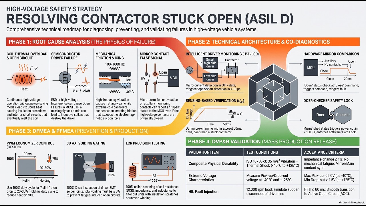
Watch the educational video on YouTube.
Frequently asked questions
What is the first check for ev contactor coil driver?
Confirm the exact command, supply, coil option, and safe measurement points before energizing anything. Then compare the expected feedback and bus-voltage response with the approved sequence.
Can auxiliary feedback prove the main contacts are healthy?
No. It reports mechanism position within its own limits. Combine it with load-side voltage, timing, and the documented circuit state.
Can I use a generic contactor driver or suppression diode?
Only after the coil, driver, polarity, release time, EMC, and protection behavior are approved together. A generic change can create slow release or false diagnostics.
What should be included in an RFQ?
Provide voltage, current waveform, switching duty, temperature, mounting, coil voltage, suppression, feedback, insulation, life, and the required drawings and test evidence.
Sources and standards context
- Texas Instruments high-voltage contactor driver note
- Texas Instruments isolated relay-welding detection note
- Fluke clamp-accessory current measurement guide
Standards, safety rules, and supplier ratings change by market and product revision. Use the current edition adopted by the project and obtain the full requirements through the responsible engineering and compliance process.





