簡単な回答: A battery string contactor connects one battery string to a shared BESS DC bus only after the controller proves compatible voltage, polarity, insulation, precharge, and communications. In parallel racks, it also isolates a faulty or serviced string without allowing the remaining strings to back-feed it. Safe operation depends on coordinated sequencing, current-sharing limits, string fuses, voltage sensing, feedback diagnostics, and controlled discharge.
このガイドでは、このトピックをレビュー可能な BESS の設計、導入、および調達のワークフローに変換します。本ガイドでは、実際の Sayoon コントローラーをビジュアルな製品リファレンスとして使用し、すべての評価、シーケンス、および安全上の決定は最終的なシステムおよび現在のメーカーのドキュメントにリンクされています。.
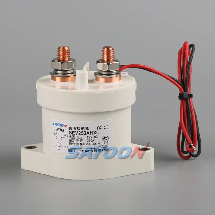
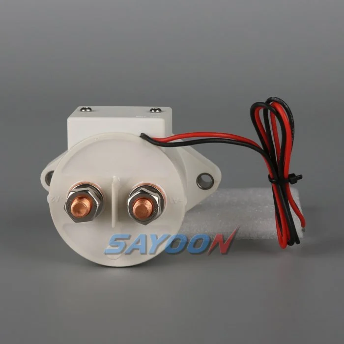
エンジニアリングの意思決定マップ
| システム状態 | 予想される電気状態 | デザインの重点 |
|---|---|---|
| String offline | Both mains open; bus may remain live | Prove isolation on both sides |
| プレチャージ | Precharge path active; mains open | Limit equalization current and verify voltage |
| Parallel online | Mains closed after voltage match | Monitor string current and sharing |
| String fault | Affected string opens; others remain controlled | Coordinate contactor, fuse, PCS, and discharge |
製品の参照と範囲
その SEV250AHXL sealed high-voltage DC contactor これは関連する実製品ファミリーの例です。レビュー 高電圧DCコンタクタ用ガイド そして DCコンタクタ選定ガイド より広範なワークフローのために。視覚的なマッチングや定格電流では、BESSに適合するモデルは認められません。電圧、伝送電流、動作動作、極性、絶縁性、温度、環境、寿命、取り付け、ドライバー、および保護を合わせて確認してください。.
Why each string needs a controlled boundary
Parallel battery strings share a bus but do not remain identical. State of charge, temperature, internal resistance, cable resistance, and aging change each string voltage and current. A battery string contactor gives the BMS a controlled boundary for startup, fault containment, maintenance, and availability management. It is not a replacement for the string fuse and cannot correct cell imbalance.
The one-line diagram should show positive and negative mains, precharge branch, fuse, service disconnect, voltage and current sensors, insulation monitoring, auxiliary feedback, and the shared PCS connection. Mark every section that can remain energized when a single string is offline.
Match voltage before paralleling
Closing two strings with different open-circuit voltages can create a large equalization current limited mainly by impedance. Before closure, compare string voltage and bus voltage with sensors that have known accuracy and timing. Confirm polarity and communications. Use precharge or another approved matching method where required.
The acceptance window must include sensor error, contactor timing, capacitance, cable impedance, and the BMS strategy. A fixed delay does not prove voltage match. If the bus is outside the approved window, stop the sequence, identify the energizing source, and prevent repeated closure attempts.
Sequence the contactors and precharge path
A typical sequence verifies interlocks and insulation, closes the designated return path, activates precharge, watches bus voltage rise, closes the main path, then opens or de-energizes the precharge branch as designed. The exact order depends on the system. Document the expected voltage and feedback after every step.
On shutdown, reduce PCS current when possible, open the required mains, confirm current stops, and verify the isolated side. The shared bus can stay energized from other strings, so pack-side and bus-side measurements are both necessary.
Manage current sharing after closure
Once parallel, current does not divide perfectly. A lower-resistance or higher-voltage string can take more charge or discharge current. Monitor each string rather than relying only on total PCS current. Set warning and trip logic from validated battery and conductor limits, including sensor uncertainty and transient sharing.
Investigate persistent imbalance through state of charge, cell temperature, contact resistance, fuse and busbar joints, cable length, sensor calibration, and BMS estimates. Do not repeatedly open and close a string to force sharing unless the approved control strategy specifically supports that behavior.
Isolate faults without creating another fault
A string overcurrent, insulation fault, thermal event, communications loss, or contactor mismatch may require isolation. The controller must decide whether to reduce PCS power first, open the affected string, or shut the common bus. Opening under current must remain within the contactor duty and protection concept.
Other strings can feed the fault through the bus until the isolation and fuse sequence completes. Calculate prospective current and clearing energy. Preserve first-fault timing so the team can distinguish a battery fault from a welded contactor, failed driver, or incorrect current sensor.
Detect welded and stuck-open conditions
Compare contactor command, coil current, auxiliary feedback, string current, string voltage, and bus voltage. A closed auxiliary contact does not prove low-resistance main conduction. An open auxiliary contact does not prove that bus voltage has disappeared. Evaluate the complete circuit, including a parallel back-feed path.
After an open command, a persistent current is strong evidence of an unintended path. Similar voltage on both sides may be normal when the shared bus remains energized and the isolated string voltage is close, so use an approved diagnostic stimulus or discharge path rather than voltage equality alone.
Commission strings one at a time
Commission with production-intent racks, busbars, controllers, sensors, fuses, and PCS. Verify polarity, part numbers, drawings, terminal torque, coil supply, suppression, auxiliary logic, and sensor calibration before energizing. Bring one string online through the complete sequence while recording synchronized waveforms.
Repeat for each physical position, then test parallel connection, controlled removal of one string, communication loss, low control voltage, sensor faults, failed precharge, emergency stop, and restart restrictions. Use authorized procedures for hazardous energy and do not bypass interlocks to accelerate testing.
Document the operating envelope
Record the number of strings, battery voltage range, permissible voltage mismatch, charge and discharge currents, transient sharing, current at make and break, precharge capacitance and resistance, fault current, fuse clearing, temperature, enclosure, conductor resistance, switching cycles, coil driver, feedback, and service strategy.
The SEV250AHXL shown here is a product-family reference. Confirm the final part number and product-specific data for the real string duty. Keep calculations, raw waveforms, settings, deviations, and approvals with the as-built configuration.
Manage changes and periodic checks
Review the original evidence whenever cell chemistry, string count, PCS firmware, cable length, busbar, fuse, cooling, sensor calibration, contactor coil, driver suppression, or operating schedule changes. A physically interchangeable part can alter current sharing, pickup margin, release time, or fault coordination. Identify the affected assumptions and repeat the necessary tests.
During maintenance, inspect terminal joints, barriers, conductors, heat evidence, contamination, mounting, control wiring, and diagnostic history. Compare voltage drop and temperature only under comparable current and measurement conditions. After replacement work, exercise the complete approved sequence under representative load and confirm that one isolated string cannot be energized through the common bus or an auxiliary path. Record the reviewer and final disposition.
安全と証拠管理
バッテリー、一般用バス、コンバータコンデンサ、並列ラック、補助電源、およびテスト機器は、承認された担当者がサイトアイソレーション手順を実施し、評価機器で必要な状態を確認するまで、危険なエネルギー源として扱ってください。フィードバックピンをブリッジしたり、コイルを強制したり、HVロックを解除したり、資格外のスイッチング動作を行う機器を開放したりしないでください。簡略化した回路図では、BESSは明らかにしない方向から電源投入されることがあります。.
正確な製品データ、承認済みのシステム要件、および代表的なテストから構築承認の基準を確立します。完全な発注コード、図面の改訂、コイルオプション、端子マップ、導体配置、計測機器の位置、校正、温度、ソフトウェアバージョン、生の波形、合格/不合格基準、偏差、および審査員を記録します。測定された事実を解釈から分離します。証拠が不足している場合は、通常の値を入力するのではなく、オープンアクションを記録します。.
関連するエンジニアリングガイド
使用する プリチャージ抵抗のサイズガイド, コンタクタのフィードバックの妥当性に関するガイド, 短絡耐性ガイド, 、および 断熱調整ガイド 補完的なチェックとして。これらのページにはさまざまな決定事項が取り上げられており、同じ承認されたシステム境界に適用されるべきです。.
教育ビデオ
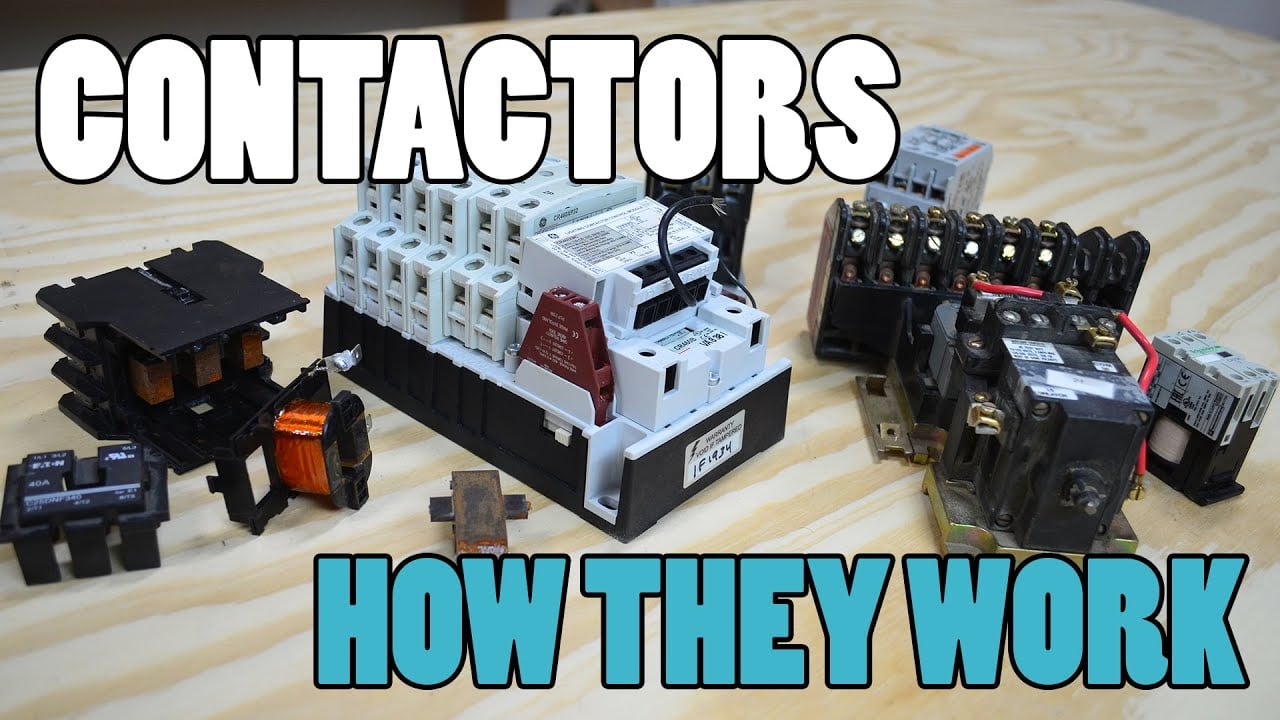
電磁接触器(コンタクタ)とは何か、そしてその仕組み Electrician U が提供するこの資料は、コンタクタの動作と高電圧スイッチングに関する視覚的な背景を提供します。この資料は、書面による設計要件や製品固有の検証に代わるものではありません。.
よくある質問
What is the first rule for battery string contactor?
回路境界とそれを駆動できるすべてのソースを定義し、測定された電圧および電流波形に基づいてそのデバイスの正確な動作を確認します。.
補助フィードバックがメインのコンタクトが開いていることを証明できるでしょうか?
いいえ。補助状態をバス電圧、串電流、コイル電流、タイミング、およびすべての可能なバックフィード経路に関連付けます。.
コンタクタはストリングヒューズの代わりになりますか?
いいえ。コンタクタは制御されたスイッチングを提供しますが、ヒューズは故障電流の保護を提供します。その耐電圧およびクリアリング機能は調整する必要があります。.
BESSコンタクタのRFQにはどのようなデータが含まれるべきですか?
電圧範囲、電流波形、作動モード、電流方向、プリチャージ、故障電流、保護、温度、取り付け、コイル制御、フィードバック、および耐用目標などを含める。.
権威ある参考文献
- OSHA 1910.147 — 危険なエネルギーの制御
- OSHA 1910.333 — 電気工事の実施手順
- IEC 60947-4-1 — コンタクタおよびモータースタータ
- 米国エネルギー省 — エネルギー貯蔵
プロジェクトで採用されたエディションと要件を使用してください。標準や製品データは変更される場合がありますので、最終的な設計を確認する必要があります。.





