A battery contactor for a commercial energy storage container must be sized from the DC bus maximum voltage, continuous current at PCS operating points, parallel string contribution, switching duty including service disconnect, and precharge coordination — not from container nameplate kW alone.
This guide is for BESS integrators and EPC teams translating container electrical diagrams into a contactor specification procurement can release. For main-circuit integration steps, see the HVDC contactor integration checklist for BESS. Review UPS and energy storage applications on SAYOON’s site for programme positioning.
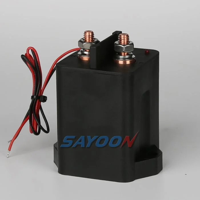
Part 1. What does a battery contactor do in a commercial BESS container?
A battery contactor is the controlled DC switch that connects or isolates the container battery strings from the power conversion system (PCS) DC bus under normal operation, service, or fault-driven commands. In containerized BESS, it sits on the main path where integrators need documented voltage class, continuous current, and switching duty — not a generic motor-branch device.
Readers searching battery contactor on commercial storage programmes are usually past definitions. They need container-level inputs that map to a datasheet line item EPC and utility reviewers can audit.
| Main-path element | Role in container | Typical owner |
|---|---|---|
| Battery contactor(s) | Connect/isolate strings to PCS bus | Integrator BMS / EMS |
| Precharge branch | Limit inrush onto PCS DC capacitance | Sequenced control |
| DC breaker or fuse | Clear fault energy | Protection study |
| Service disconnect routine | Maintenance isolation | O&M procedure |
The high-voltage system overview at BatteryDesign.net describes controlled contactors on HV DC paths — architecture language to align with your single-line, not a substitute for container fault studies.
Part 2. Which container inputs must be defined before sizing?
Freeze inputs that appear on the container electrical diagram and the PCS interface specification. Without them, two suppliers can both quote the same ampere label yet fail your bus voltage or service-cycling requirement.
Container input checklist
| Input | Why it matters | Example record field |
|---|---|---|
| Maximum DC bus voltage | Sets contact voltage class | 1500 V max during charge |
| Continuous charge current | Thermal class on inbound path | 280 A per container |
| Continuous discharge current | Thermal class on outbound path | 320 A per container |
| Parallel container count on bus | Aggregated current at tie point | 4 containers, 2 active |
| PCS manufacturer and DC limits | Defines operating corners | Vendor DC map sheet |
| Service disconnect operations | Electrical life target | 2 cycles/month maintenance |
| Ambient inside container | Derating | 45 °C max enclosure |
NREL’s battery energy storage overview frames container systems as combined battery, conversion, and protection assets — useful context when procurement asks why contactor sizing cannot stop at nameplate kW.
Part 3. How should teams set voltage class and continuous current?
Contact voltage class must cover the highest sustained potential on the switched net, including charge tolerance your EMS defines. Continuous current must reflect PCS operating points at the contactor node — not inverter AC nameplate alone.

Sizing sequence
- Record maximum DC bus voltage from EMS and PCS datasheets.
- Map continuous charge and discharge current per container at rated PCS DC voltage.
- Add parallel contribution if multiple containers share a tie bus before the contactor.
- Compare candidate devices using published continuous current at your duty category.
- Cross-check rupture or interrupt lines only when your protection study assigns opening duty to the contactor.
Published SAYOON HEV200 parameters should be quoted only from the live product table when your RFQ fits that envelope. For OEM field audits on HV datasheets, use the high voltage DC contactor OEM specification audit checklist in parallel.
| Planning question | Document location | Common gap |
|---|---|---|
| AC kW to DC current conversion | PCS DC map | Using AC nameplate only |
| Regenerative or bidirectional peaks | EMS limits | Ignoring charge-path current |
| Redundant contactor architecture | Single-line revision | Single pole without study |
| Branch vs main contactor role | Protection diagram | Mixing roles on one SKU |
Lower-current branch examples appear in 250 A DC contactor storage branch context — apply only when the switched net truly operates at that class.
Part 4. How do duty cycle and precharge affect battery contactor selection?
Duty cycle captures how often the contactor switches under load or during service. Precharge limits inrush before main contacts close onto PCS DC capacitance. Container programmes that skip either field often discover contact welding or shortened electrical life after commissioning.
Precharge coordination minimums
- Target precharge voltage threshold on the PCS bus
- Maximum precharge time before mains close or timeout fault
- Which device owns precharge resistor or active limiter (may be separate from main contactor SKU)
- Whether main contactor opens only after current falls post-PCS shutdown
Main and precharge functions may use separate devices. Document roles on the schematic before copying one part number to both nets.
Part 5. What environmental and service factors change container ratings?
Commercial containers expose contactors to enclosure temperature, humidity, vibration during transport, and maintenance cycling distinct from daily PCS dispatch. IP class, sealing technology, and mounting orientation belong on the same RFQ as electrical fields.
Integrator forums repeatedly note service disconnect cycling as a separate wear driver from daily charge/discharge switching. Capture both on the duty record.
| Factor | Container impact | RFQ line |
|---|---|---|
| Enclosure max temperature | Thermal derating | Ambient range |
| Road transport vibration | Mechanical stress | Shock class if required |
| Coastal or humid sites | Sealing | IP and coating |
| Maintenance lockout | Manual operation count | Cycles per year |
Part 6. What RFQ table validates a battery contactor shortlist for containers?
| RFQ field | Container value | Supplier value | Pass / review |
|---|---|---|---|
| Maximum DC bus voltage | (fill) | (fill) | |
| Continuous charge/discharge current | (fill) | (fill) | |
| Switching operations (service + ops) | (fill) | (fill) | |
| Precharge owner and threshold | (fill) | (fill) | |
| IP / sealing class | (fill) | (fill) | |
| Auxiliary feedback requirement | (fill) | (fill) | |
| Stated compliance scope | (fill) | (fill) |
When RFQ current and voltage fit published HEV bounds, compare HEV Series HV DC contactors and cite parameters on candidates such as the HEV200 high-voltage DC contactor.
Fit Boundary: Catalog parameters support component selection. They do not replace utility interconnection fault studies or container-level homologation evidence.
Part 7. What sizing mistakes appear on commercial BESS programmes?
- kW nameplate without PCS DC current — contactor undersized on charge path.
- Single ampere label across parallel containers — tie-bus current ignored.
- Precharge omitted from sequence chart — inrush trips PCS or welds contacts.
- Service cycling omitted — electrical life fails within first maintenance season.
- Branch contactor reused on main bus — voltage class collapse.
When RFQ lines remain incomplete, send container single-line and PCS ratings for engineering confirmation rather than approving a partial table.
References
- BatteryDesign.net — High Voltage System — DC main-path architecture
- NREL — Battery Energy Storage — container system context
- IEC 60947-4-1 scope — contactor utilisation category framing
FAQ
How do you size a contactor for a battery energy storage system?
Start from maximum DC bus voltage, continuous current at PCS charge and discharge points, switching duty including service disconnect, precharge coordination, and environmental class. Document each field on the RFQ before comparing supplier ampere labels.
What is a battery contactor in a BESS container?
It is the controlled DC switch on the main path between container battery strings and the PCS DC bus, specified for voltage class, continuous current, duty, and feedback — not a generic auxiliary relay.
What voltage and current ratings matter for storage contactors?
Contact voltage class must cover the maximum sustained DC potential on the switched net. Continuous current must reflect PCS DC operating points at the contactor node, including parallel container contribution where applicable.
Do commercial BESS containers need separate main and precharge contactors?
Many architectures use separate main and precharge paths or devices. Document which SKU owns each function on the schematic before PO release.
What RFQ data should EPC teams send for battery contactor selection?
Container single-line diagram, PCS DC voltage map, charge and discharge current, string and parallel count, service disconnect routine, IP class, auxiliary feedback needs, and target compliance scope.
When should integrators escalate to engineering review?
Escalate when bus voltage, fault duty, or environmental class exceeds published catalog bounds, when utility fault studies assign opening duty to the contactor, or when redundant poles are required without a documented protection concept.
How does container sizing differ from amp-only selection guides?
Container sizing ties PCS DC behaviour, parallel contribution, precharge, and service cycling to the main-path contactor. Amp-only guides address branch current classes without container integration context.





