A contactor acts as an electrically controlled switch that opens or closes a power circuit when its coil receives a control signal. It lets a comparatively small command circuit control equipment such as a motor, pump, heater, or lighting load without making that command signal carry the load itself. The sections below trace that control-to-load relationship, the usual operating sequence, the parts worth recognizing, and the next step when the requirement is for DC switching.
What Is a Contactor?
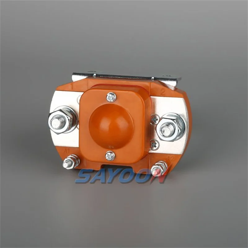
By electrically controlling the main contacts, a contactor makes or breaks a power circuit. In its common electromagnetic form, a coil creates magnetic action that changes the state of those contacts, so the power path can be commanded from a separate control circuit.
That distinction is the useful starting point. The control circuit is the command side: it tells the device when to act.
The load / power circuit is the path that carries power to the equipment. AutomationDirect’s overview of contactors describes this class of device as a specialized relay for switching power loads, while Schneider Electric’s introduction shows the same coil-and-contacts idea in a beginner-friendly form.
One community description calls a contactor an “electrical valve.” The analogy is not a design rule, but it is a helpful mental picture: the control signal moves a mechanism, and that mechanism changes the main on/off path. That is why a contactor appears in an assembly even when a person never operates the power path directly.
What Does a Contactor Do Between the Control Circuit and the Load?
The control circuit commands the coil, while the main contacts change the separate load path. This arrangement allows a panel command, controller output, or other control signal to start and stop a power load through the contactor.
Consider a pump motor or a bank of industrial lighting. The system needs a repeatable command to turn the load on or off; the contactor is the switching component that responds to that command.
It does not turn the control circuit into the load circuit. Instead, the coil’s magnetic action operates the main contacts that make or break the power path.
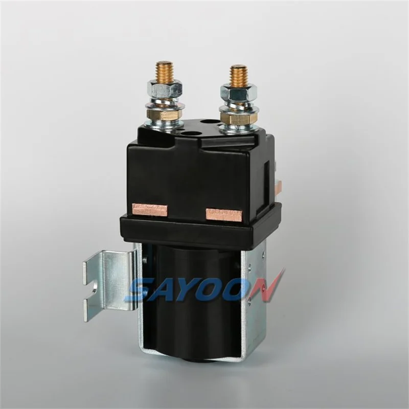
This separation also explains why product descriptions distinguish a coil or actuator from main contacts. A coil is part of the control-side action.
Main contacts are the load-carrying switching path. Auxiliary contacts, when present, are separate low-current contacts used for signalling or feedback rather than the main power path.
How Does a Standard Electromagnetic Contactor Work?
Energizing the coil moves the contact mechanism; when coil power is removed, the return mechanism releases the contacts in standard electromagnetic designs. The working principle of contactor operation is therefore a mechanical sequence driven by an electrical command.
- The control circuit energizes the coil.
- Magnetic action pulls the moving mechanism, often described as the armature.
- The moving contacts change state against the fixed contacts, making or breaking the load circuit as designed.
- When the coil is de-energized, the return mechanism releases the contact mechanism in a standard electromagnetic contactor.
This is the core answer to “how does a contactor work?” The Electrical Technology construction explainer is useful here because it separates the fixed contacts, moving contacts, armature, and spring action. In plain language, the coil pulls the switch mechanism into action, and the return action brings it back when that command is removed.
Power-duty contactors also incorporate measures to manage the arc produced as contacts open. That is an important part of why a contactor is a purpose-built switching component, but it does not turn every contactor into a complete protective device or make a generic component suitable for every circuit.
Which Parts Matter When You Read a Contactor?
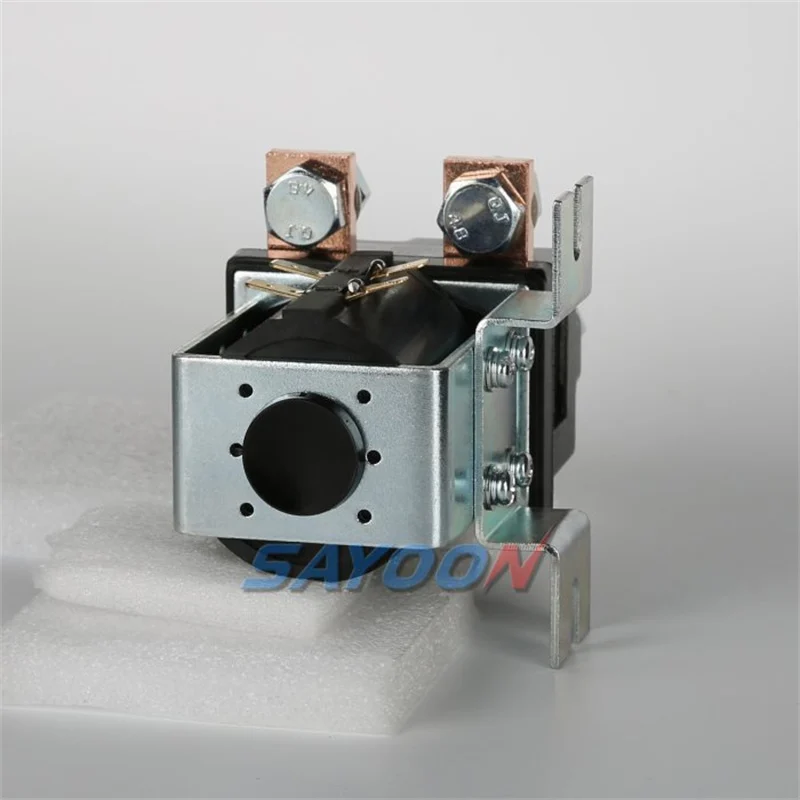
The key parts to identify are the coil, main contacts, moving mechanism, return action, enclosure, and any auxiliary contacts. Recognizing these terms makes a catalogue description easier to read because each describes a different job inside or around the switching action.
| Part | Its job in the switching action | Plain-language translation |
|---|---|---|
| Coil / electromagnet | Receives the control command and creates the magnetic action that moves the mechanism. | The part that pulls the switch mechanism into action. |
| Main contacts | Make or break the load-carrying power path. | The main on/off path for the load. |
| Armature and return spring | Transfer coil-driven motion to the contact system, then release it after coil power is removed in a standard electromagnetic design. | The moving piece and spring action that bring the switch back. |
| Enclosure / housing | Holds and protects the component assembly. | The outer body around the working parts. |
| Auxiliary contacts | Provide a separate low-current contact path for signalling or feedback. | Extra status contacts, not the main load switch. |
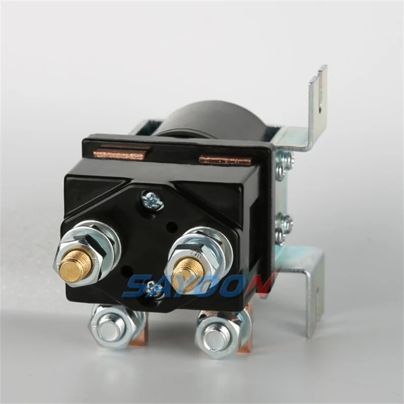
External views do not reveal every internal detail, and construction varies by model. Still, the vocabulary is practical when comparing a drawing or datasheet. A reader can tell whether a product page or datasheet is describing the command side, the power path, a feedback contact, or the physical mounting form instead of treating every terminal as the same feature.
Where Are Contactors Used?
Contactors commonly appear wherever a control signal must command a power load, including industrial-control and motor-control assemblies. Motors, pumps, compressors, heaters, and lighting are familiar examples in introductory contactor references.
The application name tells you why a contactor might be present, not whether a particular model fits that project. An OEM may see one in a pump assembly because the pump needs a commanded switching path; a panel builder may see one near lighting or heating equipment for the same broad reason. AutomationDirect’s contactor overview uses motors, lighting, and heating as familiar examples of the loads a contactor can switch.
For a purchasing conversation, the useful move is to separate the application from the component decision. First identify what is being switched and how it is commanded.
Then compare the selected device’s contact arrangement, operating data, drawing, and system requirements. That prevents a general example such as “pump” from being mistaken for a ready-made product recommendation.
Contactor vs. Relay: What Is the Practical Difference?
Comparing a contactor with a relay starts with intended duty, contact arrangement, and the selected device’s ratings rather than one universal cutoff. Calling a contactor simply a bigger relay skips the questions that actually determine whether the device belongs in the circuit.
In everyday descriptions, the names serve as useful shorthand. Contactors are commonly discussed in connection with power-load switching and arc management, while relays are often encountered in lower-power control or signalling work.
But the boundary is not safely expressed as a single number. If a bill of materials uses both names, compare what each selected device is intended to switch and what contact configuration the circuit needs.
| Component | Primary job | What to compare before treating it as interchangeable |
|---|---|---|
| Contactor | Commanded switching of a power circuit | Intended load duty, contact form, operating data, and the selected model’s drawing. |
| Relay | Electrically controlled switching or signalling | Contact arrangement and the actual duty of the selected relay. |
| Fuse | Overcurrent protection by interrupting its own element under fault conditions | The circuit’s protection design; it is not a commanded on/off switch. |
| Circuit breaker | Protective interruption and circuit control within its design role | The selected breaker’s protective and switching functions in the complete circuit. |
The distinction matters when a buyer sees a contactor and a relay listed beside each other. Choosing based only on a generic label can hide an unsuitable contact form or duty. The selected product documentation is where that comparison becomes concrete.
What a Contactor Does Not Replace
A contactor performs commanded switching, while protective devices have different jobs in the complete circuit. It should not be described as a replacement for a fuse or circuit breaker simply because all three appear in electrical assemblies.
The circuit breaker / fuse comparison is about different functions, not a choice between equivalent names for the same device.
Important: A contactor’s job is to respond to a command and change the power path. Overcurrent and short-circuit protection are separate functions that must be addressed by the circuit’s wider design. Source: contactor overview
This distinction answers a common search question without turning a definition article into a protection-design procedure. If the immediate question is contactor versus breaker in a DC energy-storage context, see DC contactor vs. circuit breaker in BESS.
For the foundational point, keep the roles separate: the contactor is the commanded switching element; the protection scheme is broader than that one component.
Where Do DC Contactors Fit in a SAYOON Enquiry?
A DC switching requirement should move from the general concept to the needed contact form and a model-specific drawing and datasheet review. Once the reader knows what the contactor is doing in the circuit, the next question is not “which contactor is biggest?” but whether the required main path is normally open or normally closed and what the selected model documents.
When comparing normally open / normally closed contact forms, begin with the required resting main-path state. For a normally-open main-path requirement, SAYOON lists the CZW50A normally-open DC contactor with a 1 NO contact form for DC control applications.
Where the requirement explicitly calls for a normally-closed main path, the SZJB300A-D normally-closed DC contactor is listed with a 1 NC contact form. Those are model-specific examples, not a substitute for reviewing the current drawing and datasheet for the selected product.
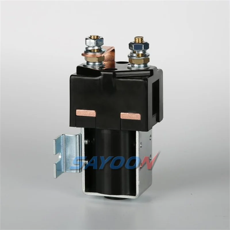
For the next product-level step, start with the SAYOON DC contactor product families. This range overview is the appropriate continuation after identifying the required contact form; it does not imply that one pictured contactor fits every circuit.
If you are still interpreting NO and NC terminology, the related guide on NO/NC contactor configuration in DC panels keeps that subject separate from this definition explainer. Coil selection is likewise its own decision; see DC contactor coil selection when the coil requirement is known.
FAQ
What is the purpose of a contactor?
The purpose of a contactor is to let a control circuit command the making or breaking of a power circuit. It is used where an electrical command needs to operate a power-load switching path rather than directly carry that load.
How does a contactor work?
In a standard electromagnetic contactor, the control circuit energizes a coil. The coil’s magnetic action moves the contact mechanism, which changes the main contacts; removing coil power allows the return mechanism to release the contacts.
What are the main parts of a contactor?
The parts most often named are the coil, main contacts, moving mechanism or armature, return mechanism, enclosure, and any auxiliary contacts. The main contacts handle the load path, while auxiliary contacts are used for separate signalling or feedback functions.
Is a contactor the same as a relay?
No. Both are electrically controlled switches, but the terms do not create a universal divide based on one rating. Compare the selected device’s intended duty, contact configuration, and documentation before treating one as an interchangeable replacement for the other.
Is a contactor a fuse or circuit breaker?
No. A contactor is a commanded switching component. A fuse and a circuit breaker serve protective roles within the complete circuit, so they should not be treated as the same component or as interchangeable functions.
What is the difference between NO and NC on a contactor?
Normally open and normally closed describe the stated resting contact condition for the selected contact form. For DC products, confirm the requirement against the selected model’s drawing and datasheet; SAYOON’s CZW50A is listed with 1 NO, while SZJB300A-D is listed with 1 NC.
Can a contactor be used for DC?
Yes, DC contactors are made for DC-control applications, but the general contactor definition does not choose a model for a specific circuit. Start with the required contact form and then review the selected product’s current drawing and datasheet.
How do you test a contactor?
Testing depends on the equipment, the contactor type, and the service context, so this article does not provide a field procedure. For a high-level DC-specific troubleshooting route, read how to test a DC contactor safely.





