Respuesta rápida: A battery string contactor connects one battery string to a shared BESS DC bus only after the controller proves compatible voltage, polarity, insulation, precharge, and communications. In parallel racks, it also isolates a faulty or serviced string without allowing the remaining strings to back-feed it. Safe operation depends on coordinated sequencing, current-sharing limits, string fuses, voltage sensing, feedback diagnostics, and controlled discharge.
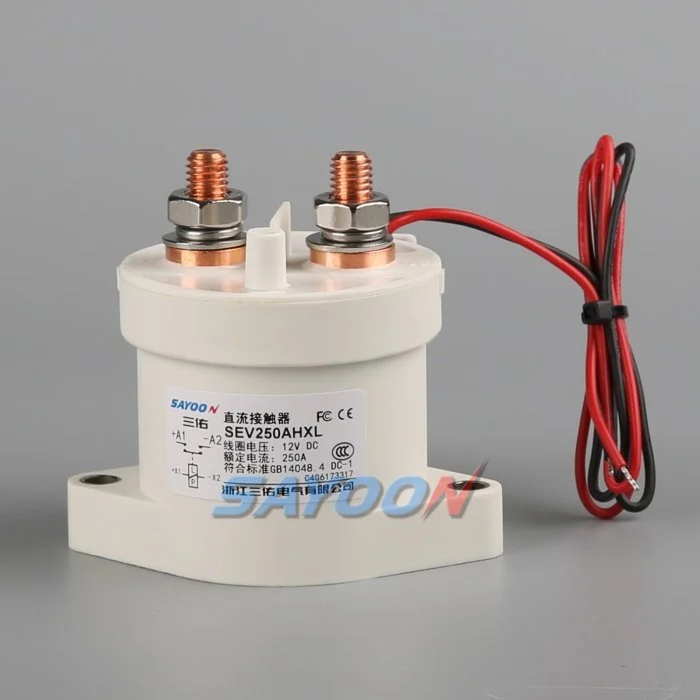
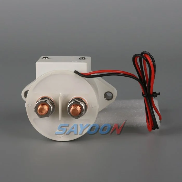
Esta guía convierte el tema en un flujo de trabajo revisable para el diseño, puesta en marcha y adquisición de BESS. Utiliza como referencia visual al propio contactor Sayoon, manteniendo todos los valores, órdenes de secuencia y decisiones de seguridad vinculados al sistema final y a la documentación actual del fabricante.
Mapa de decisiones de ingeniería
| Estado del sistema | Condición eléctrica esperada | Foco en el diseño |
|---|---|---|
| String offline | Both mains open; bus may remain live | Prove isolation on both sides |
| Precarga | Precharge path active; mains open | Limit equalization current and verify voltage |
| Parallel online | Mains closed after voltage match | Monitor string current and sharing |
| String fault | Affected string opens; others remain controlled | Coordinate contactor, fuse, PCS, and discharge |
Referencia y ámbito del producto
El SEV250AHXL sealed high-voltage DC contactor es un ejemplo relevante de una familia de productos reales. Verifique Guías de contacto de alto voltaje de tipo DC y Guía de selección de contactores de CC para el flujo de trabajo más amplio. Una coincidencia visual o un valor nominal de corriente no avalan un modelo para un BESS. Confirma la tensión, el corriente a transportar, el régimen de carga y desconexión, la polaridad, la aislación, la temperatura, el entorno, la vida útil, el montaje, el accionador y la protección.
Why each string needs a controlled boundary
Parallel battery strings share a bus but do not remain identical. State of charge, temperature, internal resistance, cable resistance, and aging change each string voltage and current. A battery string contactor gives the BMS a controlled boundary for startup, fault containment, maintenance, and availability management. It is not a replacement for the string fuse and cannot correct cell imbalance.
The one-line diagram should show positive and negative mains, precharge branch, fuse, service disconnect, voltage and current sensors, insulation monitoring, auxiliary feedback, and the shared PCS connection. Mark every section that can remain energized when a single string is offline.
Match voltage before paralleling
Closing two strings with different open-circuit voltages can create a large equalization current limited mainly by impedance. Before closure, compare string voltage and bus voltage with sensors that have known accuracy and timing. Confirm polarity and communications. Use precharge or another approved matching method where required.
The acceptance window must include sensor error, contactor timing, capacitance, cable impedance, and the BMS strategy. A fixed delay does not prove voltage match. If the bus is outside the approved window, stop the sequence, identify the energizing source, and prevent repeated closure attempts.
Sequence the contactors and precharge path
A typical sequence verifies interlocks and insulation, closes the designated return path, activates precharge, watches bus voltage rise, closes the main path, then opens or de-energizes the precharge branch as designed. The exact order depends on the system. Document the expected voltage and feedback after every step.
On shutdown, reduce PCS current when possible, open the required mains, confirm current stops, and verify the isolated side. The shared bus can stay energized from other strings, so pack-side and bus-side measurements are both necessary.
Manage current sharing after closure
Once parallel, current does not divide perfectly. A lower-resistance or higher-voltage string can take more charge or discharge current. Monitor each string rather than relying only on total PCS current. Set warning and trip logic from validated battery and conductor limits, including sensor uncertainty and transient sharing.
Investigate persistent imbalance through state of charge, cell temperature, contact resistance, fuse and busbar joints, cable length, sensor calibration, and BMS estimates. Do not repeatedly open and close a string to force sharing unless the approved control strategy specifically supports that behavior.
Isolate faults without creating another fault
A string overcurrent, insulation fault, thermal event, communications loss, or contactor mismatch may require isolation. The controller must decide whether to reduce PCS power first, open the affected string, or shut the common bus. Opening under current must remain within the contactor duty and protection concept.
Other strings can feed the fault through the bus until the isolation and fuse sequence completes. Calculate prospective current and clearing energy. Preserve first-fault timing so the team can distinguish a battery fault from a welded contactor, failed driver, or incorrect current sensor.
Detect welded and stuck-open conditions
Compare contactor command, coil current, auxiliary feedback, string current, string voltage, and bus voltage. A closed auxiliary contact does not prove low-resistance main conduction. An open auxiliary contact does not prove that bus voltage has disappeared. Evaluate the complete circuit, including a parallel back-feed path.
After an open command, a persistent current is strong evidence of an unintended path. Similar voltage on both sides may be normal when the shared bus remains energized and the isolated string voltage is close, so use an approved diagnostic stimulus or discharge path rather than voltage equality alone.
Commission strings one at a time
Commission with production-intent racks, busbars, controllers, sensors, fuses, and PCS. Verify polarity, part numbers, drawings, terminal torque, coil supply, suppression, auxiliary logic, and sensor calibration before energizing. Bring one string online through the complete sequence while recording synchronized waveforms.
Repeat for each physical position, then test parallel connection, controlled removal of one string, communication loss, low control voltage, sensor faults, failed precharge, emergency stop, and restart restrictions. Use authorized procedures for hazardous energy and do not bypass interlocks to accelerate testing.
Document the operating envelope
Record the number of strings, battery voltage range, permissible voltage mismatch, charge and discharge currents, transient sharing, current at make and break, precharge capacitance and resistance, fault current, fuse clearing, temperature, enclosure, conductor resistance, switching cycles, coil driver, feedback, and service strategy.
The SEV250AHXL shown here is a product-family reference. Confirm the final part number and product-specific data for the real string duty. Keep calculations, raw waveforms, settings, deviations, and approvals with the as-built configuration.
Manage changes and periodic checks
Review the original evidence whenever cell chemistry, string count, PCS firmware, cable length, busbar, fuse, cooling, sensor calibration, contactor coil, driver suppression, or operating schedule changes. A physically interchangeable part can alter current sharing, pickup margin, release time, or fault coordination. Identify the affected assumptions and repeat the necessary tests.
During maintenance, inspect terminal joints, barriers, conductors, heat evidence, contamination, mounting, control wiring, and diagnostic history. Compare voltage drop and temperature only under comparable current and measurement conditions. After replacement work, exercise the complete approved sequence under representative load and confirm that one isolated string cannot be energized through the common bus or an auxiliary path. Record the reviewer and final disposition.
Control de la seguridad y la evidencia
Trate la batería, los condensadores comunes, los convertidores, los racks paralelos, los suministros auxiliares y el equipo de prueba como fuentes de energía peligrosas hasta que una persona autorizada haya aplicado el procedimiento de aislamiento del sitio y verifique el estado requerido con instrumentos de medición homologados. No debe conectar pines de retroalimentación, forzar una bobina, deshabilitar los interbloques de alta tensión ni abrir un dispositivo fuera de su ámbito de funcionamiento homologado. Un BESS puede seguir estando alimentado desde una dirección que no queda clara en un esquema simplificado.
Generar límites de aceptación basados en los datos exactos del producto, los requisitos del sistema aprobados y las pruebas representativas. Registre el código completo de pedido, la revisión del dibujo, la opción de bobina, el mapa de terminales, la disposición de los conductores, las ubicaciones de los instrumentos, la calibración, la temperatura, la versión del software, las formas de onda sin procesar, los criterios de aprobación/rechazo, las desviaciones y los revisores. Separe los datos medidos de las interpretaciones. Cuando faltan pruebas, registre una acción abierta en lugar de introducir un valor estándar.
Guías de ingeniería relacionadas
Utiliza el Guía de dimensionamiento del resistor de carga preinstalada, Guía de plausibilidad de los comentarios del contactor, Guía de resistencia a los cortocircuitos, y Guía de coordinación de aislamiento como comprobaciones complementarias. Estas páginas cubren diferentes decisiones y deberían aplicarse al mismo límite de sistema aprobado.
Video educativo
¿Qué es un contactor y cómo funciona? El manual de instrucciones de Electrician U proporciona una visión general de la operación del contactor y la conmutación de alta tensión. No sustituye a los requisitos de diseño escritos ni a la validación específica del producto.
Mira el video educativo en YouTube.
Preguntas frecuentes
What is the first rule for battery string contactor?
Defina los límites del circuito y cada fuente que pueda generarlo, luego verifique la exactitud del dispositivo en función de las formas de onda de voltaje y corriente medidas.
¿Puede la retroalimentación auxiliar demostrar que los contactos principales están abiertos?
No. Relacione el estado auxiliar con la tensión del bus, la corriente de la cuerda, la corriente de la bobina, el tiempo de funcionamiento y todos los posibles caminos de retroalimentación.
¿Debería un contactor reemplazar un fusible de cadena?
No. Un contactor proporciona un conmutador controlado, mientras que un fusible proporciona protección contra el flujo de corriente defectuoso. Sus funciones de resistencia y desconexión deben coordinarse.
¿Qué datos deben incluirse en la solicitud de presupuesto para el contacto de un BESS?
Incluya el rango de voltaje, las formas de onda de corriente, el modo de funcionamiento de corte y conexión, la dirección de la corriente, la carga previa, el corriente de fallo, la protección, la temperatura, el montaje, el control de bobina, el retroalimento y el objetivo de vida útil.
Referencias autorizadas
- OSHA 1910.147 — Control de la energía peligrosa
- OSHA 1910.333 — prácticas de trabajo eléctrico
- IEC 60947-4-1 — contactores y arrancadores de motor
- Departamento de Energía de los Estados Unidos — almacenamiento de energía
Utilice las ediciones y requisitos adoptados por el proyecto. Los estándares y los datos del producto pueden cambiar, por lo que el equipo de ingeniería responsable debe confirmar el diseño final.





