簡単な回答: An EV contactor life calculation should divide the vehicle duty into distinct switching events, apply the manufacturer’s electrical-endurance data at the actual DC voltage and current, account for temperature, inrush, breaking direction, and fault exposure, and then validate the result with representative testing. Mechanical cycle life cannot be substituted for electrical life because arcing and contact heating dominate when load is switched.
このエンジニアリングガイドは、バッテリーパック、BMS、テスト、調達、サービスチーム向けのレビュー可能な一連の作業へとこのトピックを変換します。このガイドは、実際の製品ファミリーを参考として使用し、すべての評価と安全上の決定は最終的な用途と現在のメーカーのドキュメントにリンクされています。.
決定マップ
| 動作状態 | 期待される証拠 | エンジニアリングへの重点 |
|---|---|---|
| Normal key-on/off | Low current after correct precharge and torque removal | Largest cycle count; verify sequence remains controlled |
| Charging connection | Bidirectional current and repeated sessions | Voltage window, current direction, temperature |
| Emergency opening | Higher current or abnormal voltage | Separate qualified duty; do not average into normal cycles |
| No-load diagnostics | Mechanism operates with minimal main current | Counts toward mechanical life, not the same wear per cycle |
製品の参照と適用範囲
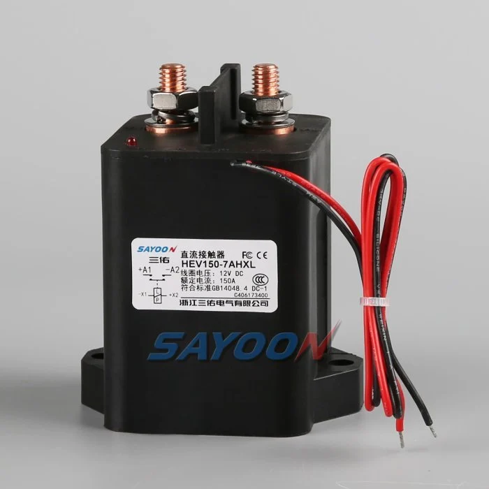
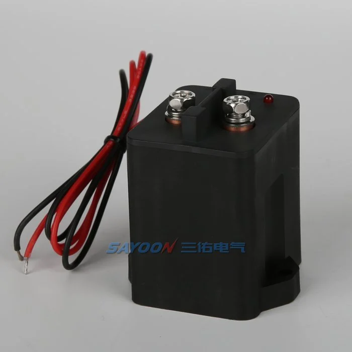
その HEV150 high-voltage sealed DC contactor ここでは、本物のSayoon製品の参考資料を示しています。レビューはこちら 高電圧DCコンタクタの範囲 隣接する電流クラスについて。画像とファミリ名は、特定の車両の承認を意味するものではありません。最終的な部品番号、コイルオプション、図面、電気的用途、絶縁性、環境適応性、耐用年数、および保護機能の調整は、合わせて検討する必要があります。.
Mechanical life versus electrical life
Mechanical life describes operations with little or no main-contact current under stated conditions. Electrical life describes operations while making, carrying, or breaking a specified load. In an EV pack, the mechanism may survive far more cycles than the contacts can endure under DC arcing. Use mechanical life to check wear from diagnostic exercises and key cycles, but use electrical-endurance evidence for current-carrying events.
The catalogue value is valid only for its test voltage, current, load type, switching frequency, ambient condition, conductor arrangement, and failure criterion. Do not scale it by current alone or assume that half the rated current automatically doubles life.
Build a mission profile
Estimate vehicle years, operating days, trips per day, charge sessions, service events, diagnostic cycles, and abnormal shutdowns. For each event, record whether the contactor makes current, carries current, or breaks current; the voltage and current at the instant of transition; polarity; duration; temperature; and precharge state. Group similar events into bins rather than using one average cycle.
A simple planning total is N_total = years × operating days per year × events per day, but that number is only the start. A life model must preserve the different wear severity of normal zero-current opening, capacitive make, regenerative current, and emergency interruption.
Estimate wear with duty bins
For each validated duty bin, divide the planned number of events by the demonstrated endurance for that exact or conservatively bounding condition. Summing those fractions can be used as an engineering screening index: D = Σ(nᵢ / Nᵢ). If D approaches one, the planned duty consumes the demonstrated endurance. This is not a universal physical law and should not replace supplier data or qualification testing; it is a traceable way to combine approved test points.
Example inputs should come from measured vehicle traces and manufacturer curves. If no endurance point bounds a severe event, mark the result unavailable and request testing. Never invent an Nᵢ value from a nominal current rating.
Precharge and make-current control
Incorrect precharge can dominate contact wear. An inverter DC link initially appears as a capacitive load, so closing the main contactor before the voltage difference is reduced creates a high make pulse. Verify the resistor value, pulse energy, timeout, and measured voltage ratio. Count failed or repeated precharge attempts because they can create more severe events than normal starts.
A contactor that carries 150 A continuously may still be damaged by a much shorter uncontrolled inrush. Separate carry heating from make erosion in the review. The precharge controller should use measured voltage rather than a fixed delay alone.
Breaking current and arc energy
DC current has no natural zero crossing, so voltage, current, circuit inductance, polarity, arc-control structure, and opening speed influence interruption wear. Normal software should remove torque or charging current before opening when the safety concept permits. Emergency opening must be treated as a separate qualified event with its own limit and expected count.
Do not average one high-current break into hundreds of no-load operations. If a crash device or fuse is intended to clear the severe fault, document the coordination and the residual duty the contactor must survive.
Temperature, resistance and installation
Contact heating is related to current squared times resistance. Ambient temperature, enclosure airflow, terminal torque, busbar support, conductor size, and neighboring heat sources change the contact temperature and therefore the life margin. Record contact resistance and terminal temperature on new samples and after endurance blocks.
A rising voltage drop can indicate wear or a loose connection, but the measurement method must exclude cable and joint resistance. Use consistent four-wire points where practical and define the acceptance limit from approved product data.
Validation and confidence
Run representative duty sequences on production-intent contactors, drivers, busbars, and protection hardware. Include cold and hot starts, supply tolerance, vibration, and the switching waveforms that drive the life model. Inspect timing, contact resistance, temperature rise, insulation, and failure modes at planned intervals. Test multiple samples so one favorable unit is not treated as a population guarantee.
Compare measured wear with the calculation, revise the duty bins, and retain the evidence with the vehicle program. Add margin for uncertainty, manufacturing variation, and foreseeable retries.
RFQ data for a life review
Send the battery voltage range, current traces at make and break, continuous duty, switching frequency, event counts, current direction, DC-link capacitance, precharge sequence, fault-clearing strategy, temperature, vibration, mounting, conductor size, coil driver, and target years. Ask the supplier to identify which endurance data applies and what additional qualification is needed.
The HEV150 shown here is a real product reference. Final life approval requires the exact model, coil option, duty, and installation—not a visual match or headline ampere rating.
受入記録
完全な部品番号、図面のバージョン、コイルオプション、端子機能、電圧範囲、電流波形、スイッチング状態、プリチャージおよび放電の詳細、ドライバーおよび抑制機能、補助ロジック、HVIL状態、保護、周囲温度および筐体温度、取り付け方向、導体およびバスバーの詳細、計測機器の位置、校正ステータス、ソフトウェアバージョン、および通過/不通過の制限値を含む1つの制御レコードを作成します。 カタログ値の測定値と異なる値を分離し、一般的な値の追加ではなく、欠落した証拠を「未処理」としてマークします。.
重要な境界におけるテスト:コイルの低圧および高圧供給、低温および高温環境、最長承認済みハーネス、繰り返しサイクル、および安全概念に記載された異常状態。一次基準時間でコマンド、コイル電圧および電流、補助フィードバック、パック電圧、負荷側電圧、および障害フラグの記録。説明不明な不適合後に自動再試行を停止、蓄電されたエネルギーを隔離、および最初の障害の証拠を保持する。セットアップと端子配置の写真を撮影し、すべてのプローブポイントを識別し、保管されたハーネスおよびバスバーを記録し、各しきい値が安全である理由を説明する。熱安定化後の代表的なサンプルと計画された耐久ブロック後のサンプルを繰り返す。オペレータ、テスト日、サンプル識別、および生産アセンブリからのすべての逸脱を記録する。後続の正常なサイクルで同様の基準値と比較できる。これらは、交換サンプル、サプライヤーの修正、ファームウェアのアップデート、またはハーネスの変更を、同様に承認された基準値と比較できるようにする。.
関連するSayoonガイド
使用する DCコンタクタ選定ガイド, セーフコンタクターテストワークフロー, 、および 開閉時間ガイド 補完的な決定のため。 feedback plausibility guide explains command, auxiliary, and bus-voltage correlation.
教育ビデオ
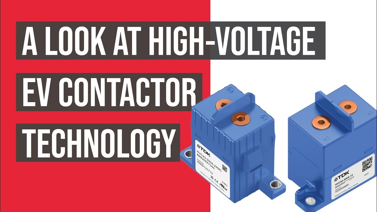
A Look At High-Voltage EV Contactor Technology by CHARGED Electric Vehicles Magazine provides visual background related to this engineering review. It does not replace the written requirements, product data, or vehicle safety procedure.
よくある質問
What is the most important check for ev contactor life calculation?
最大電圧と実効スイッチング波形から始め、その後、正確なコンタクタデータ、制御シーケンス、設置、および故障挙動を確認します。.
補助連絡担当者がメイン連絡担当者が健康であることを証明できるだろうか?
いいえ。補助フィードバックレポートの仕組みは限界にまで限定されています。バス電圧、タイミング、コイル電流、および回路状態を独立した証拠として使用してください。.
定格電流を完全な選択基準として使用することは可能でしょうか?
いいえ。連続電流、誘導電流、断路電流、電圧、温度、極性、寿命、絶縁性、および保護の調整は、別々の条件です。.
RFQとともに送付すべき情報は何か?
電圧および電流の波形、スイッチングシーケンス、環境、コイルおよびドライバの詳細、フィードバックロジック、保護、取り付け、耐用年数目標、および必要な試験証拠を送信してください。.
権威ある参考文献
- IEC 60947-4-1 contactor and motor-starter standard page
- Texas Instruments high-voltage contactor driver note
- NREL vehicle technologies research
車両プログラムで採用された仕様および要件を使用してください。標準やサプライヤーのデータは変更される場合があります。責任あるエンジニアリングチームは最終設計を確認する必要があります。.





