Быстрый ответ: An EV contactor life calculation should divide the vehicle duty into distinct switching events, apply the manufacturer’s electrical-endurance data at the actual DC voltage and current, account for temperature, inrush, breaking direction, and fault exposure, and then validate the result with representative testing. Mechanical cycle life cannot be substituted for electrical life because arcing and contact heating dominate when load is switched.
Этот инженерный руководство превращает эту тему в последовательность шагов для команд по разработке аккумуляторных батарей, BMS, тестированию, закупкам и обслуживанию. В нем используется реальная линейка продукции в качестве основы, при этом все оценки и решения по безопасности связаны с конечной целью применения и текущими документами производителя.
Карта решений
| Оперативное состояние | Ожидаемые доказательства | Сфокусированность на инженерных разработках |
|---|---|---|
| Normal key-on/off | Low current after correct precharge and torque removal | Largest cycle count; verify sequence remains controlled |
| Charging connection | Bidirectional current and repeated sessions | Voltage window, current direction, temperature |
| Emergency opening | Higher current or abnormal voltage | Separate qualified duty; do not average into normal cycles |
| No-load diagnostics | Mechanism operates with minimal main current | Counts toward mechanical life, not the same wear per cycle |
Ссылка на продукт и границы его применения
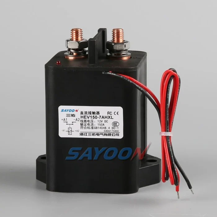
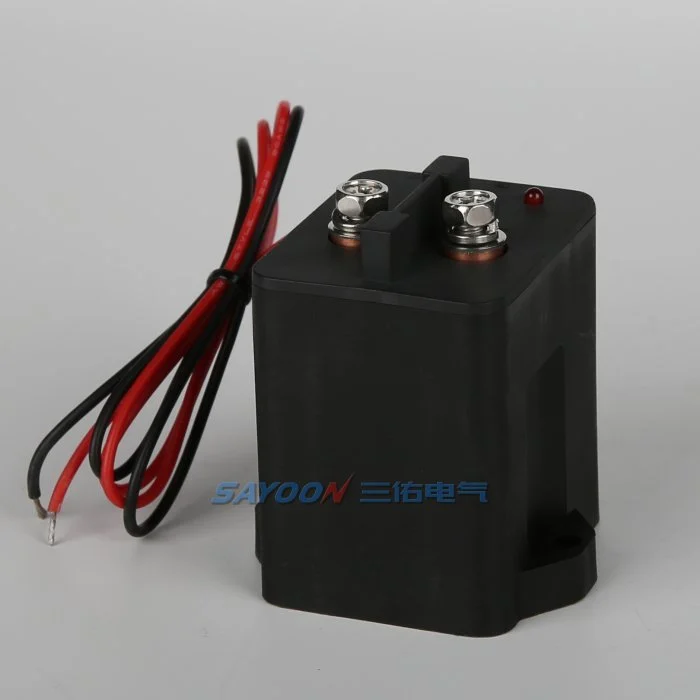
Эт HEV150 high-voltage sealed DC contactor На фото представлен настоящий образец продукции Sayoon. Проверьте сеть высоконапряжных контакторов постоянного тока для смежных классов токов. Изображение и название семейства не устанавливают одобрения для конкретного транспортного средства. Финальную цифру номера, вариант катушки, чертеж, электрическая нагрузка, изоляция, среда обитания, срок службы и согласование защиты необходимо рассматривать вместе.
Mechanical life versus electrical life
Mechanical life describes operations with little or no main-contact current under stated conditions. Electrical life describes operations while making, carrying, or breaking a specified load. In an EV pack, the mechanism may survive far more cycles than the contacts can endure under DC arcing. Use mechanical life to check wear from diagnostic exercises and key cycles, but use electrical-endurance evidence for current-carrying events.
The catalogue value is valid only for its test voltage, current, load type, switching frequency, ambient condition, conductor arrangement, and failure criterion. Do not scale it by current alone or assume that half the rated current automatically doubles life.
Build a mission profile
Estimate vehicle years, operating days, trips per day, charge sessions, service events, diagnostic cycles, and abnormal shutdowns. For each event, record whether the contactor makes current, carries current, or breaks current; the voltage and current at the instant of transition; polarity; duration; temperature; and precharge state. Group similar events into bins rather than using one average cycle.
A simple planning total is N_total = years × operating days per year × events per day, but that number is only the start. A life model must preserve the different wear severity of normal zero-current opening, capacitive make, regenerative current, and emergency interruption.
Estimate wear with duty bins
For each validated duty bin, divide the planned number of events by the demonstrated endurance for that exact or conservatively bounding condition. Summing those fractions can be used as an engineering screening index: D = Σ(nᵢ / Nᵢ). If D approaches one, the planned duty consumes the demonstrated endurance. This is not a universal physical law and should not replace supplier data or qualification testing; it is a traceable way to combine approved test points.
Example inputs should come from measured vehicle traces and manufacturer curves. If no endurance point bounds a severe event, mark the result unavailable and request testing. Never invent an Nᵢ value from a nominal current rating.
Precharge and make-current control
Incorrect precharge can dominate contact wear. An inverter DC link initially appears as a capacitive load, so closing the main contactor before the voltage difference is reduced creates a high make pulse. Verify the resistor value, pulse energy, timeout, and measured voltage ratio. Count failed or repeated precharge attempts because they can create more severe events than normal starts.
A contactor that carries 150 A continuously may still be damaged by a much shorter uncontrolled inrush. Separate carry heating from make erosion in the review. The precharge controller should use measured voltage rather than a fixed delay alone.
Breaking current and arc energy
DC current has no natural zero crossing, so voltage, current, circuit inductance, polarity, arc-control structure, and opening speed influence interruption wear. Normal software should remove torque or charging current before opening when the safety concept permits. Emergency opening must be treated as a separate qualified event with its own limit and expected count.
Do not average one high-current break into hundreds of no-load operations. If a crash device or fuse is intended to clear the severe fault, document the coordination and the residual duty the contactor must survive.
Temperature, resistance and installation
Contact heating is related to current squared times resistance. Ambient temperature, enclosure airflow, terminal torque, busbar support, conductor size, and neighboring heat sources change the contact temperature and therefore the life margin. Record contact resistance and terminal temperature on new samples and after endurance blocks.
A rising voltage drop can indicate wear or a loose connection, but the measurement method must exclude cable and joint resistance. Use consistent four-wire points where practical and define the acceptance limit from approved product data.
Validation and confidence
Run representative duty sequences on production-intent contactors, drivers, busbars, and protection hardware. Include cold and hot starts, supply tolerance, vibration, and the switching waveforms that drive the life model. Inspect timing, contact resistance, temperature rise, insulation, and failure modes at planned intervals. Test multiple samples so one favorable unit is not treated as a population guarantee.
Compare measured wear with the calculation, revise the duty bins, and retain the evidence with the vehicle program. Add margin for uncertainty, manufacturing variation, and foreseeable retries.
RFQ data for a life review
Send the battery voltage range, current traces at make and break, continuous duty, switching frequency, event counts, current direction, DC-link capacitance, precharge sequence, fault-clearing strategy, temperature, vibration, mounting, conductor size, coil driver, and target years. Ask the supplier to identify which endurance data applies and what additional qualification is needed.
The HEV150 shown here is a real product reference. Final life approval requires the exact model, coil option, duty, and installation—not a visual match or headline ampere rating.
Документы о признании
Создайте один управляемый регистр, содержащий полную информацию о номере детали, версии чертежа, опции для катушек, функциональных возможностях терминала, диапазоне напряжения, форме тока, состоянии переключения, деталях предварительного заряда и разряда, драйвере и подавном устройстве, вспомогательной логике, состоянии HVIL, защите, температуре окружающей среды и корпуса, ориентации крепления, деталях проводника и распределительной шины, местоположения приборов, статусе калибровки, версии программного обеспечения и ограничениях пропуска/отрицания. Отдельно отслеживайте измеренные значения от значений из каталога и укажите отсутствующие данные как открытую задачу, а не вставляйте типичное значение.
Проверьте те параметры, которые имеют значение: низкое и высокое напряжение в цепи питания, условия холода и тепла, максимальная разрешенная длина шнура, повторные циклы и ненормальное состояние, указанное в концепции безопасности. Запишите данные о команде остановки, напряжении и токе в цепи питания, вспомогательной обратной связи, напряжении в аккумуляторной батарее, напряжении в нагрузке и проблемах с показателями на одном таймере. Прекратите автоматические повторные попытки после неполадок, вызванных необъяснимыми обстоятельствами, изолируйте накопленную энергию и сохраните данные о первых проблемах. Сфотографируйте схему установки и расположение выводов, идентифицируйте все точки зонда, запишите схему аккумуляторной батареи и распределительную шину и объясните, почему каждый порог является безопасным. После термостабилизации и после запланированного периода испытаний повторите испытание на репрезентативной выборке. Включите оператора, дату испытания, идентификацию образца, а также любые отклонения от утвержденного набора. После последующего успешного испытания не следует стереть предыдущую ошибку. Эти данные позволяют сравнить новый образец с ранее зарегистрированными данными, а также с исходным набором данных, разработанным поставщиком.
Связанные статьи Сайун
Используйте Руководство по выбору контакторов постоянного тока, безопасный рабочий процесс проверки контактора, и Руководство по времени открытия и закрытия для принятия дополнительных решений. feedback plausibility guide explains command, auxiliary, and bus-voltage correlation.
Обучающее видео
A Look At High-Voltage EV Contactor Technology by CHARGED Electric Vehicles Magazine provides visual background related to this engineering review. It does not replace the written requirements, product data, or vehicle safety procedure.
Посмотрите обучающее видео на YouTube.
Часто задаваемые вопросы
What is the most important check for ev contactor life calculation?
Начните с максимального напряжения и реального импульса переключения, а затем проверите точность данных контактора, последовательность управления, установку и поведение при неисправности вместе.
Может ли вспомогательный контакт подтвердить, что основные контакты здоровы?
Нет. Механизм отчетности о вспомогательной подаче обратной связи работает в рамках своих ограничений. В качестве независимых факторов используются напряжение на шине, время срабатывания, ток на катушке и состояние схемы.
Можно ли использовать номинальный ток в качестве основного критерия выбора?
Нет. Постоянный ток, малый ток, перепад напряжения, температура, полярность, срок службы, изоляция и координация защиты — это отдельные условия.
Какие сведения следует включать в запросе о закупке?
Отправьте данные о токовом и напряжённом токах, последовательности переключений, условиях эксплуатации, характеристиках катушки и драйвера, логике обратной связи, защите, монтаже, целевом сроке службы и требуемых испытательных данных.
Авторитетные источники
- IEC 60947-4-1 contactor and motor-starter standard page
- Texas Instruments high-voltage contactor driver note
- NREL vehicle technologies research
Используйте версию и требования, утвержденные программой автомобиля. Стандарты и данные поставщика могут измениться, и ответственная инженерная команда должна подтвердить окончательный проект.





