Snel antwoord: An EV contactor life calculation should divide the vehicle duty into distinct switching events, apply the manufacturer’s electrical-endurance data at the actual DC voltage and current, account for temperature, inrush, breaking direction, and fault exposure, and then validate the result with representative testing. Mechanical cycle life cannot be substituted for electrical life because arcing and contact heating dominate when load is switched.
Deze technische gids zet het onderwerp om in een herhaalbare volgorde voor batterijpacks, BMS'en, tests, sourcing en serviceafdelingen. Het maakt gebruik van de echte productfamilie als referentie, terwijl elke beoordeling en veiligheidsbeslissing is gekoppeld aan de uiteindelijke toepassing en de huidige fabrikadoppervlakken.
Besluitkaart
| Werkende toestand | Onderzochte gegevens | Engineeringfocus |
|---|---|---|
| Normal key-on/off | Low current after correct precharge and torque removal | Largest cycle count; verify sequence remains controlled |
| Charging connection | Bidirectional current and repeated sessions | Voltage window, current direction, temperature |
| Emergency opening | Higher current or abnormal voltage | Separate qualified duty; do not average into normal cycles |
| No-load diagnostics | Mechanism operates with minimal main current | Counts toward mechanical life, not the same wear per cycle |
Productreferentie en toepassingsgrenzen
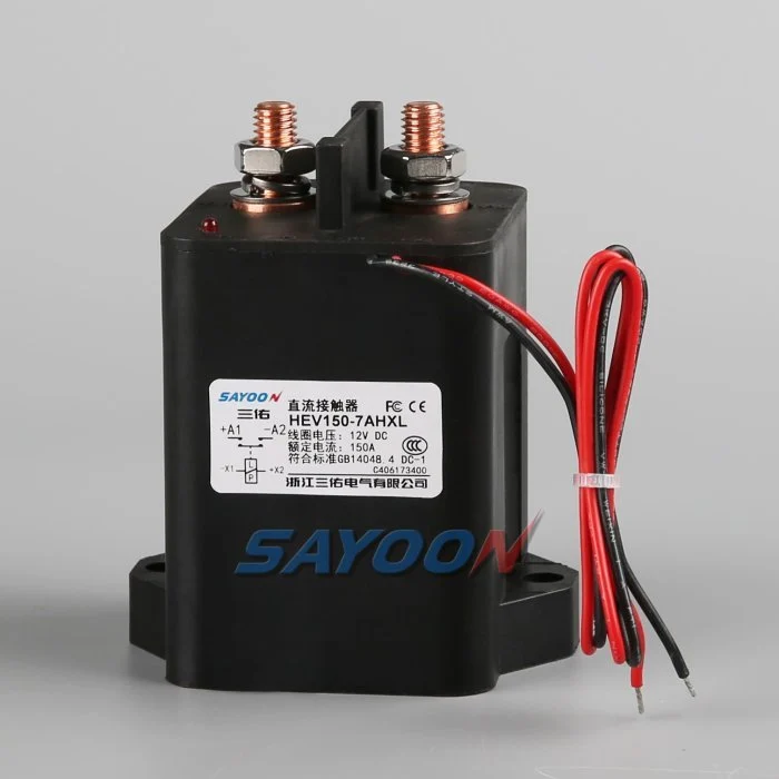
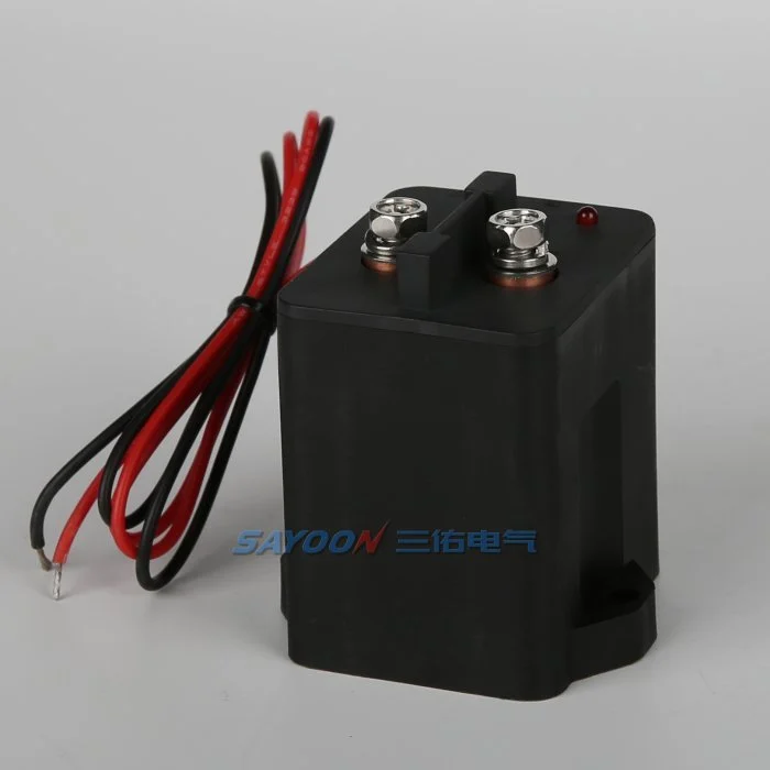
De HEV150 high-voltage sealed DC contactor Het hier getoonde is een echt referentieproduct van Sayoon. Bekijk de Uitgebreid assortiment hoogspannings-DC-contactoren Voor naastgelegen stroomklassen. Het beeld en de familienaam geven geen goedkeuring voor een bepaald voertuig aan. Het definitieve onderdeelnummer, de coiloptie, de tekening, de elektrische belasting, de isolatie, het milieu, de levensduur en de coördinatie van de bescherming moeten samen worden beoordeeld.
Mechanical life versus electrical life
Mechanical life describes operations with little or no main-contact current under stated conditions. Electrical life describes operations while making, carrying, or breaking a specified load. In an EV pack, the mechanism may survive far more cycles than the contacts can endure under DC arcing. Use mechanical life to check wear from diagnostic exercises and key cycles, but use electrical-endurance evidence for current-carrying events.
The catalogue value is valid only for its test voltage, current, load type, switching frequency, ambient condition, conductor arrangement, and failure criterion. Do not scale it by current alone or assume that half the rated current automatically doubles life.
Build a mission profile
Estimate vehicle years, operating days, trips per day, charge sessions, service events, diagnostic cycles, and abnormal shutdowns. For each event, record whether the contactor makes current, carries current, or breaks current; the voltage and current at the instant of transition; polarity; duration; temperature; and precharge state. Group similar events into bins rather than using one average cycle.
A simple planning total is N_total = years × operating days per year × events per day, but that number is only the start. A life model must preserve the different wear severity of normal zero-current opening, capacitive make, regenerative current, and emergency interruption.
Estimate wear with duty bins
For each validated duty bin, divide the planned number of events by the demonstrated endurance for that exact or conservatively bounding condition. Summing those fractions can be used as an engineering screening index: D = Σ(nᵢ / Nᵢ). If D approaches one, the planned duty consumes the demonstrated endurance. This is not a universal physical law and should not replace supplier data or qualification testing; it is a traceable way to combine approved test points.
Example inputs should come from measured vehicle traces and manufacturer curves. If no endurance point bounds a severe event, mark the result unavailable and request testing. Never invent an Nᵢ value from a nominal current rating.
Precharge and make-current control
Incorrect precharge can dominate contact wear. An inverter DC link initially appears as a capacitive load, so closing the main contactor before the voltage difference is reduced creates a high make pulse. Verify the resistor value, pulse energy, timeout, and measured voltage ratio. Count failed or repeated precharge attempts because they can create more severe events than normal starts.
A contactor that carries 150 A continuously may still be damaged by a much shorter uncontrolled inrush. Separate carry heating from make erosion in the review. The precharge controller should use measured voltage rather than a fixed delay alone.
Breaking current and arc energy
DC current has no natural zero crossing, so voltage, current, circuit inductance, polarity, arc-control structure, and opening speed influence interruption wear. Normal software should remove torque or charging current before opening when the safety concept permits. Emergency opening must be treated as a separate qualified event with its own limit and expected count.
Do not average one high-current break into hundreds of no-load operations. If a crash device or fuse is intended to clear the severe fault, document the coordination and the residual duty the contactor must survive.
Temperature, resistance and installation
Contact heating is related to current squared times resistance. Ambient temperature, enclosure airflow, terminal torque, busbar support, conductor size, and neighboring heat sources change the contact temperature and therefore the life margin. Record contact resistance and terminal temperature on new samples and after endurance blocks.
A rising voltage drop can indicate wear or a loose connection, but the measurement method must exclude cable and joint resistance. Use consistent four-wire points where practical and define the acceptance limit from approved product data.
Validation and confidence
Run representative duty sequences on production-intent contactors, drivers, busbars, and protection hardware. Include cold and hot starts, supply tolerance, vibration, and the switching waveforms that drive the life model. Inspect timing, contact resistance, temperature rise, insulation, and failure modes at planned intervals. Test multiple samples so one favorable unit is not treated as a population guarantee.
Compare measured wear with the calculation, revise the duty bins, and retain the evidence with the vehicle program. Add margin for uncertainty, manufacturing variation, and foreseeable retries.
RFQ data for a life review
Send the battery voltage range, current traces at make and break, continuous duty, switching frequency, event counts, current direction, DC-link capacitance, precharge sequence, fault-clearing strategy, temperature, vibration, mounting, conductor size, coil driver, and target years. Ask the supplier to identify which endurance data applies and what additional qualification is needed.
The HEV150 shown here is a real product reference. Final life approval requires the exact model, coil option, duty, and installation—not a visual match or headline ampere rating.
Accreditatiegegevens
Maak een gecontroleerde record aan met het volledige onderdeelnummer, teken revisie, coil-optie, terminalfuncties, spanningsbereik, stroomgolfvorm, schakelstatus, precharge- en ontlaadgegevens, driver en suppressie, hulplogica, HVIL-status, bescherming, omgevings- en behuizingstemperaturen, montagerichting, details van geleiders en busbars, instrumentlocaties, kalibratiestatus, softwareversie en door- of niet-doorgaande limieten. Verdeel gemeten waarden af van de cataloguswaarden en markeer ontbrekende gegevens als open actie in plaats van een typische waarde toe te voegen.
Test op de belangrijkste parameters: lage en hoge spoelspanning, koude en warme omstandigheden, langste goedgekeurde kabelverbinding, herhaalde cycli en de abnormale toestand zoals omschreven in het veiligheidsconcept. Capture-commando, spoelspanning en -stroom, hulpvolgverwerking, packvoltage, laadzijdevoltage en foutmeldingen op één tijdbasis. Stop automatisch herhalingen na een onverklaarbaar mismatch, isoleer opgeslagen energie en bewaar bewijs van de eerste storing. Fotografeer de installatie en de terminalindeling, identificeer alle sondepunten, registreer de kabelverbinding en busbar volgens de productievoorgestelde configuratie en leg uit waarom elk drempelwaarde veilig is. Herhaal een representatief monster na thermische stabilisatie en na de geplande endurance-blok. Vermeld de operator, testdatum, identiteit van de monsterstalen en alle afwijkingen van de productieconfiguratie. Een later succesvol cyclus mag geen eerder probleem verwijderen. Deze gegevens maken een vervangend monster, revisie van de leverancier, firmware-update of kabelverbindingswijziging mogelijk, die vergeleken kunnen worden met dezelfde goedgekeurde basislijn.
Gerelateerde Sayoon-gidsen
Gebruik de Selectiehandleiding voor DC-relais, veilig contactor testworkflow, en Gids voor openingstijden en sluitingstijden voor aanvullende beslissingen. feedback plausibility guide explains command, auxiliary, and bus-voltage correlation.
Educatieve video
A Look At High-Voltage EV Contactor Technology by CHARGED Electric Vehicles Magazine provides visual background related to this engineering review. It does not replace the written requirements, product data, or vehicle safety procedure.
Bekijk de educatieve video op YouTube.
Veelgestelde vragen
What is the most important check for ev contactor life calculation?
Start met de maximale spanning en de werkelijke schakelgolf, controleer vervolgens samen de precieze contactorgegevens, de besturingsesequentie, de installatie en het gedrag bij storingen.
Kan een hulpcontact een bewijs leveren dat de hoofdcontacten gezond zijn?
Nee. Het mechanisme voor hulpvol feedbackrapportage blijft binnen zijn grenzen. Gebruik busspanning, timing, spoelstroom en de status van het circuit als onafhankelijke bewijzen.
Kan een nominale stroomsterkte worden gebruikt als de volledige selectieregel?
Nee. Continu stroom, stroomstoring, spanningsstoring, temperatuur, polariteit, levensduur, isolatie en beschermingscoördinatie zijn afzonderlijke vereisten.
Welke informatie moet bij een RFQ worden verstrekt?
Stuur voltage- en stroomgolven, schakelverloop, omgeving, details over spoel en driver, feedbacklogica, bescherming, montage, levensduurdoelstelling en vereiste testgegevens mee.
Betrouwbare referenties
- IEC 60947-4-1 contactor and motor-starter standard page
- Texas Instruments high-voltage contactor driver note
- NREL vehicle technologies research
Gebruik de uitvoering en vereisten die zijn vastgesteld door het voertuigprogramma. Normen en gegevens van leveranciers kunnen veranderen, en het verantwoordelijke technische team moet het definitieve ontwerp bevestigen.





