Snel antwoord: A BESS bidirectional contactor must carry charging and discharging current, but “bidirectional” also needs a precise switching definition. Confirm whether the device may make or break current in both directions, at the full DC voltage and actual circuit inductance. Then verify continuous thermal duty, precharge, fault coordination, coil control, auxiliary feedback, insulation, environment, and electrical endurance for every operating quadrant.
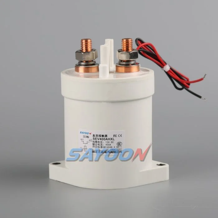
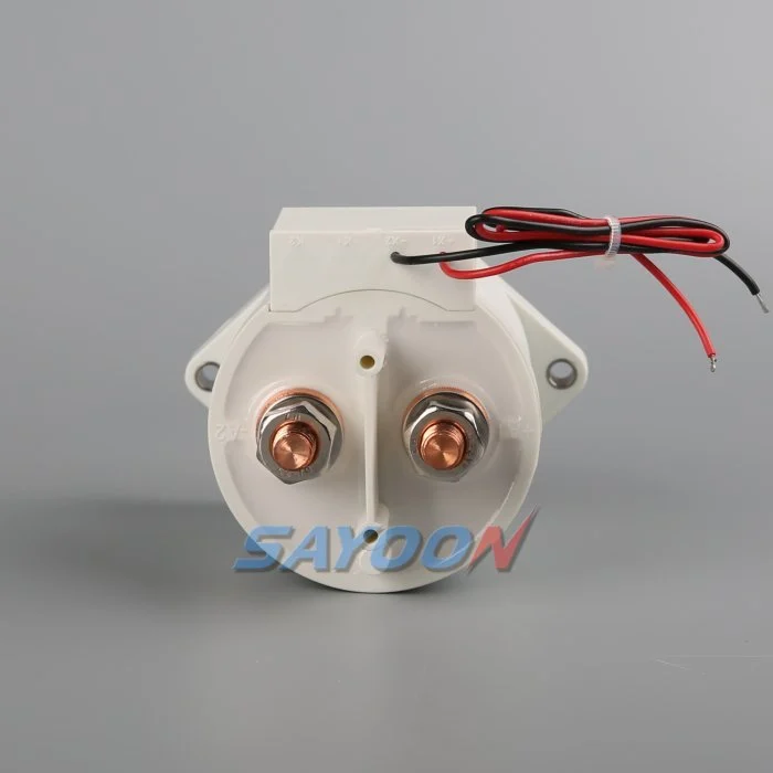
Deze handleiding zet het onderwerp om in een workflow voor het ontwerpen, inbedrijfname en het inkopen van een BESS-installatie die kan worden beoordeeld. Het gebruik maakt van een echte Sayoon-contactor als visueel referentieproduct, waarbij alle specificaties, volgorde en veiligheidsbeslissingen zijn vastgelegd in de uiteindelijke installatie en de huidige documentatie van de fabrikant.
Engineering besluitkaart
| Staat van het systeem | Onderhoudstoestand van de elektrische installatie | Designfocus |
|---|---|---|
| Charge | PCS to battery | Continuous heating, charging limits, reverse current |
| Discharge | Battery to PCS | Peak current, bus sag, terminal temperature |
| Normal opening | Current reduced before opening | Residual current and DC arc direction |
| Emergency opening | Abnormal current in either direction | Qualified break duty and fuse coordination |
Productreferentie en toepassingsgebied
De SEV400AHXL sealed high-voltage DC contactor is een relevant voorbeeld van een echt productfamilie. Bekijk de Hoogspannings-DC-contactoren en Selectiehandleiding voor DC-relais Voor de bredere workflow. Een visuele overeenstemming of nominale stroom is geen garantie voor een BESS-model. Controleer voltage, doorstroom, duty- en break-voltage, polariteit, isolatie, temperatuur, omgeving, levensduur, montage, driver en bescherming samen.
Define what bidirectional means
Current can flow toward the battery during charging and away from it during discharge. Carrying current in both directions is not the same as interrupting current in both directions. Internal magnetic arc control can make DC breaking performance polarity-sensitive even when the main terminals look symmetrical. Ask for explicit make and break data for each required direction, voltage, current, load type, and time constant.
Create an operating-state table that lists current direction at closure, during steady carry, and at opening. Include regeneration from the converter, charging from the grid, black-start behavior, DC-coupled generation, and maintenance tests. A state with nominally zero current should still specify a residual-current limit and how the controller verifies it.
Use maximum system voltage
Select against maximum charged battery voltage and defined transients, not only the nominal BESS label. The PCS can impose voltage during startup, shutdown, or a fault. Confirm which terminal may be positive in each state and whether the approved rating changes with polarity. Do not use an AC rating to infer DC interruption capability.
Insulation review covers dielectric strength, clearance, creepage, sealing, pollution, altitude, enclosure geometry, and distances to grounded metal. The completed assembly must be assessed because nearby busbars, sensors, and barriers change the effective insulation path.
Separate carry, make, and break duties
Continuous current drives I-squared-R heating. Make current depends on voltage difference, DC-link capacitance, precharge success, and circuit resistance. Break duty depends on current, voltage, inductance, polarity, contact opening, and protection action. A headline ampere rating does not combine these conditions. Use measured waveforms from charge and discharge operation.
List normal openings separately from emergency interruptions. Normal control should reduce PCS current before opening when the safety concept allows. Emergency duty may be limited to a small number of events, but it must still be supported by evidence and coordinated with the fuse or pyrofuse.
Check thermal performance in both modes
Charging and discharging may have different duration, RMS current, enclosure temperature, and cooling. Fast charging can create a long high-current period after a hot discharge. Model the full daily profile and validate it on production-intent busbars. Measure terminal and body temperatures after thermal stabilization.
Contact resistance, joint resistance, terminal torque, conductor size, surface condition, and neighboring components influence temperature. Use consistent four-wire voltage-drop points where practical. A device can meet average current yet exceed temperature limits during a stacked sequence of charge and discharge events.
Coordinate precharge and polarity
Precharge should reduce the voltage across the main contacts before closure. In a bidirectional system, either the battery or PCS side may be energized first, so the branch topology and resistor stress must be checked for both directions. Confirm blocking devices, sensing, and control logic prevent an unintended discharge through the precharge branch.
Authorize closure from measured voltage difference and stable polarity. Define the response to reversed sensor leads, a welded precharge contactor, open resistor, failed bus sensor, or externally energized PCS. Repeated failed attempts are counted in the duty profile.
Design feedback and fault logic
Auxiliary feedback reports mechanism position within its limits. Correlate it with command, coil current, pack-side voltage, bus-side voltage, and PCS current. If the commanded-open device still shows current or equalized voltage, investigate a weld, back-feed, sensor error, or parallel path. If commanded closed but current cannot flow, check the fuse, busbar, connection, and main path.
Store the first mismatch with direction, voltage, current, temperature, and timing. Avoid automatic retries when the system cannot prove an open state. Fault recovery should require controlled discharge and an explicit safe-state decision.
Validate interruption and protection
Calculate prospective fault current from battery strings and every parallel source. The contactor may only need to withstand current until the fuse clears, or it may be required to interrupt a defined current. These are different duties. Confirm the exact coordination, including current direction and available energy.
Test representative switching on production-intent hardware with the approved protection. Inspect contact resistance, timing, insulation, temperature, and physical condition before and after endurance blocks. A test at lower voltage or favorable polarity does not establish performance in the opposite quadrant.
Build the RFQ around waveforms
Provide minimum, nominal, maximum, and transient voltage; charge and discharge current traces; current at make and break; DC-link capacitance; circuit inductance; precharge; fault current; protection clearing; temperature; enclosure; altitude; vibration; mounting; busbars; coil voltage; driver; suppression; feedback; life; and required standards.
Request a drawing and product-specific evidence for both current directions. The SEV400AHXL shown here is a real product reference, not automatic approval for the application. Final selection requires the exact ordering code and verified duty.
Control changes through service life
Recheck the validated envelope when the battery configuration, PCS firmware, busbar, fuse, cooling, sensor, coil option, driver suppression, or daily operating profile changes. The contactor may look unchanged while make current, opening duty, temperature, release time, or insulation stress has changed. Compare revisions against a controlled baseline and repeat the affected calculations and tests.
During maintenance, inspect terminals, barriers, conductors, heat evidence, contamination, mounting, control wiring, and stored faults. Trend voltage drop and temperature only at comparable current and measurement points. After replacing a contactor, fuse, sensor, or controller, repeat the approved precharge, close, load, open, discharge, feedback, and restart-inhibit sequence before returning the rack to service.
Veiligheids- en bewijskwaliteitscontroles
Behandel de batterij, gemeenschappelijke bus, convertercondensatoren, parallelle rekken, hulpapparatuur en testapparatuur als gevaarlijke energiebronnen totdat een bevoegde persoon de plaatselijke isolatieprocedure heeft toegepast en de vereiste status heeft gecontroleerd met geënte instrumenten. Breng geen feedbackpinnen over, dwing geen spoel, ontgrendel geen HV-interlocks of open geen apparaat buiten zijn kwalificeerde schakelingsfunctie. Een BESS kan nog steeds worden geactiveerd vanuit een richting die niet duidelijk is in een vereenvoudigde schematische weergave.
Bouw acceptatie limieten op basis van de exacte productgegevens, goedgekeurde systeemvereisten en representatieve tests. Noteer de volledige bestelcode, teken revisie, coil optie, terminal map, geleiderarrangement, instrumentlocaties, kalibratie, temperatuur, softwareversie, ruwe golfvormen, pass/fail criteria, afwijkingen en beoordelaars. Verdeel gemeten feiten af van interpretaties. Wanneer er geen bewijs is, noteer een open actie in plaats van een typische waarde in te voeren.
Gerelateerde technische handleidingen
Gebruik de gids voor de afmetingen van precharge-weerstanden, contactor-feedback-validiteitsrichtlijn, Gids voor kortsluitbestendigheid, en Gids voor isolatiecoördinatie als aanvullende controles. Deze pagina's behandelen verschillende beslissingen en moeten worden toegepast op dezelfde goedgekeurde systeemgrenzen.
Educatieve video
A Look At High-Voltage EV Contactor Technology by CHARGED Electric Vehicles Magazine provides visual background on contactor operation and high-voltage switching. It does not replace the written design requirements or the product-specific validation.
Bekijk de educatieve video op YouTube.
Veelgestelde vragen
What is the first rule for bess bidirectional contactor?
Bepaal de circuitgrenzen en alle bronnen die deze kunnen voeden, en controleer vervolgens de exacte werking van het apparaat op basis van gemeten spannings- en stroomgolven.
Kan de hulpfunctie voor feedback aantonen dat de hoofdcontacten openstaan?
Nee. Verhoud de hulpstatus met de busspanning, de stringstroom, de spoelstroom, de timing en alle mogelijke terugstroomroutes.
Moet een contactor een touphuis vervangen?
Nee. Een contactor zorgt voor een gecontroleerde schakeling, terwijl een contactdoos foutstroombescherming biedt. Hun weerstand en ontlading moeten op elkaar afgestemd zijn.
Welke gegevens moeten in een RFQ voor een BESS-contactor staan?
Vermeld de spanningsbereik, stroomvormen, de functies voor aan- en uitschakeling, de stroomrichting, de voorlading, de foutstroom, de bescherming, de temperatuur, de montage, de spiraalregeling, de feedback en de levensduurdoelstelling.
Betrouwbare referenties
- OSHA 1910.147 — controle van gevaarlijke energie
- OSHA 1910.333 — praktijken bij elektrotechnische werkzaamheden
- IEC 60947-4-1 — contactoren en motorstarter
- Ministerie van Energie van de VS — energieopslag
Gebruik de door het project aangenomen edities en vereisten. Normen en productgegevens kunnen veranderen, dus moet het verantwoordelijke technische team het definitieve ontwerp bevestigen.





