Câu trả lời nhanh: A BESS bidirectional contactor must carry charging and discharging current, but “bidirectional” also needs a precise switching definition. Confirm whether the device may make or break current in both directions, at the full DC voltage and actual circuit inductance. Then verify continuous thermal duty, precharge, fault coordination, coil control, auxiliary feedback, insulation, environment, and electrical endurance for every operating quadrant.
Hướng dẫn này biến chủ đề này thành quy trình thiết kế, vận hành và tìm nguồn cung ứng BESS có thể đánh giá được. Nó sử dụng một thiết bị tiếp xúc thực tế của Sayoon làm tài liệu tham khảo trực quan cho sản phẩm, đồng thời đảm bảo rằng mọi đánh giá, trình tự và quyết định về an toàn đều gắn liền với hệ thống cuối cùng và tài liệu hướng dẫn của nhà sản xuất hiện tại.
Bản đồ quyết định kỹ thuật
| Trạng thái hệ thống | Điều kiện điện năng dự kiến | Tập trung vào thiết kế |
|---|---|---|
| Charge | PCS to battery | Continuous heating, charging limits, reverse current |
| Discharge | Battery to PCS | Peak current, bus sag, terminal temperature |
| Normal opening | Current reduced before opening | Residual current and DC arc direction |
| Emergency opening | Abnormal current in either direction | Qualified break duty and fuse coordination |
Tham khảo sản phẩm và phạm vi áp dụng
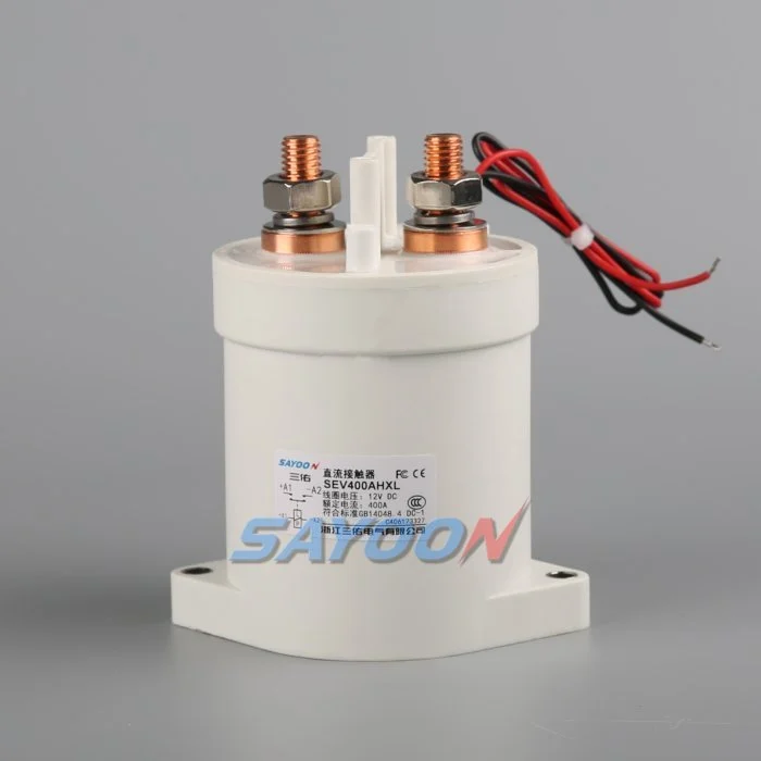
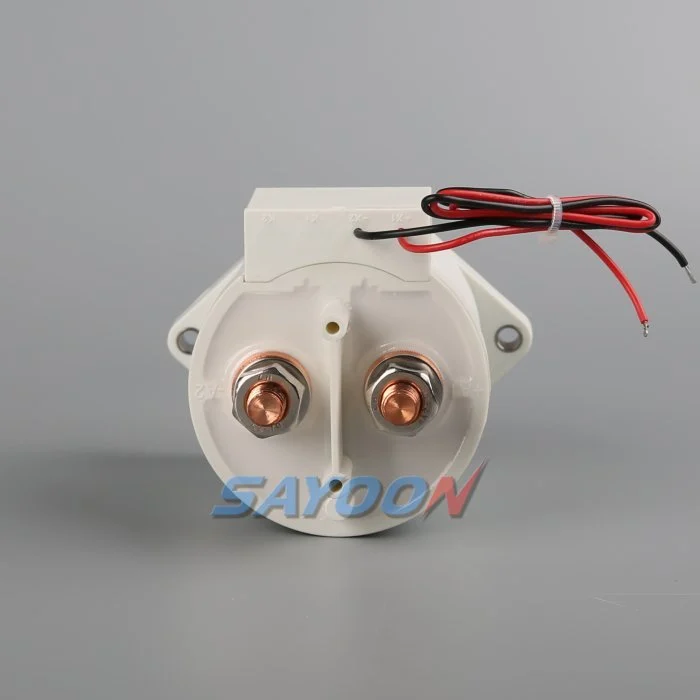
The SEV400AHXL sealed high-voltage DC contactor Đây là một ví dụ về một dòng sản phẩm thực tế có liên quan. Hãy xem xét Hướng dẫn sử dụng động cơ tiếp xúc DC điện áp cao và Hướng dẫn lựa chọn khởi động từ DC (contactor DC) Đối với quy trình làm việc tổng thể. Một kết quả tương đồng về hình thức hoặc dòng điện danh nghĩa không chứng nhận một mô hình cho BESS. Xác nhận điện áp, dòng điện tải, công suất hoạt động, cực, cách điện, nhiệt độ, môi trường, tuổi thọ, lắp đặt, thiết bị điều khiển và bảo vệ cùng nhau.
Define what bidirectional means
Current can flow toward the battery during charging and away from it during discharge. Carrying current in both directions is not the same as interrupting current in both directions. Internal magnetic arc control can make DC breaking performance polarity-sensitive even when the main terminals look symmetrical. Ask for explicit make and break data for each required direction, voltage, current, load type, and time constant.
Create an operating-state table that lists current direction at closure, during steady carry, and at opening. Include regeneration from the converter, charging from the grid, black-start behavior, DC-coupled generation, and maintenance tests. A state with nominally zero current should still specify a residual-current limit and how the controller verifies it.
Use maximum system voltage
Select against maximum charged battery voltage and defined transients, not only the nominal BESS label. The PCS can impose voltage during startup, shutdown, or a fault. Confirm which terminal may be positive in each state and whether the approved rating changes with polarity. Do not use an AC rating to infer DC interruption capability.
Insulation review covers dielectric strength, clearance, creepage, sealing, pollution, altitude, enclosure geometry, and distances to grounded metal. The completed assembly must be assessed because nearby busbars, sensors, and barriers change the effective insulation path.
Separate carry, make, and break duties
Continuous current drives I-squared-R heating. Make current depends on voltage difference, DC-link capacitance, precharge success, and circuit resistance. Break duty depends on current, voltage, inductance, polarity, contact opening, and protection action. A headline ampere rating does not combine these conditions. Use measured waveforms from charge and discharge operation.
List normal openings separately from emergency interruptions. Normal control should reduce PCS current before opening when the safety concept allows. Emergency duty may be limited to a small number of events, but it must still be supported by evidence and coordinated with the fuse or pyrofuse.
Check thermal performance in both modes
Charging and discharging may have different duration, RMS current, enclosure temperature, and cooling. Fast charging can create a long high-current period after a hot discharge. Model the full daily profile and validate it on production-intent busbars. Measure terminal and body temperatures after thermal stabilization.
Contact resistance, joint resistance, terminal torque, conductor size, surface condition, and neighboring components influence temperature. Use consistent four-wire voltage-drop points where practical. A device can meet average current yet exceed temperature limits during a stacked sequence of charge and discharge events.
Coordinate precharge and polarity
Precharge should reduce the voltage across the main contacts before closure. In a bidirectional system, either the battery or PCS side may be energized first, so the branch topology and resistor stress must be checked for both directions. Confirm blocking devices, sensing, and control logic prevent an unintended discharge through the precharge branch.
Authorize closure from measured voltage difference and stable polarity. Define the response to reversed sensor leads, a welded precharge contactor, open resistor, failed bus sensor, or externally energized PCS. Repeated failed attempts are counted in the duty profile.
Design feedback and fault logic
Auxiliary feedback reports mechanism position within its limits. Correlate it with command, coil current, pack-side voltage, bus-side voltage, and PCS current. If the commanded-open device still shows current or equalized voltage, investigate a weld, back-feed, sensor error, or parallel path. If commanded closed but current cannot flow, check the fuse, busbar, connection, and main path.
Store the first mismatch with direction, voltage, current, temperature, and timing. Avoid automatic retries when the system cannot prove an open state. Fault recovery should require controlled discharge and an explicit safe-state decision.
Validate interruption and protection
Calculate prospective fault current from battery strings and every parallel source. The contactor may only need to withstand current until the fuse clears, or it may be required to interrupt a defined current. These are different duties. Confirm the exact coordination, including current direction and available energy.
Test representative switching on production-intent hardware with the approved protection. Inspect contact resistance, timing, insulation, temperature, and physical condition before and after endurance blocks. A test at lower voltage or favorable polarity does not establish performance in the opposite quadrant.
Build the RFQ around waveforms
Provide minimum, nominal, maximum, and transient voltage; charge and discharge current traces; current at make and break; DC-link capacitance; circuit inductance; precharge; fault current; protection clearing; temperature; enclosure; altitude; vibration; mounting; busbars; coil voltage; driver; suppression; feedback; life; and required standards.
Request a drawing and product-specific evidence for both current directions. The SEV400AHXL shown here is a real product reference, not automatic approval for the application. Final selection requires the exact ordering code and verified duty.
Control changes through service life
Recheck the validated envelope when the battery configuration, PCS firmware, busbar, fuse, cooling, sensor, coil option, driver suppression, or daily operating profile changes. The contactor may look unchanged while make current, opening duty, temperature, release time, or insulation stress has changed. Compare revisions against a controlled baseline and repeat the affected calculations and tests.
During maintenance, inspect terminals, barriers, conductors, heat evidence, contamination, mounting, control wiring, and stored faults. Trend voltage drop and temperature only at comparable current and measurement points. After replacing a contactor, fuse, sensor, or controller, repeat the approved precharge, close, load, open, discharge, feedback, and restart-inhibit sequence before returning the rack to service.
Kiểm soát an toàn và bằng chứng
Đối xử với pin, tụ đồng bộ, tụ biến áp, giá đỡ song song, vật tư phụ trợ và thiết bị thử nghiệm như các nguồn năng lượng nguy hiểm cho đến khi một người được ủy quyền áp dụng quy trình cách ly vị trí và xác nhận trạng thái cần thiết bằng các thiết bị có hiệu suất. Không nối tiếp các chân tiếp nhận tín hiệu, không ép buộc cuộn dây, không phá vỡ các rào cản điện áp cao và không mở thiết bị ngoài phạm vi chức năng chuyển mạch được cấp phép. Một BESS có thể vẫn duy trì trạng thái hoạt động từ một hướng không rõ ràng trên sơ đồ điện đơn giản.
Xây dựng các giới hạn chấp nhận dựa trên dữ liệu chính xác của sản phẩm, các yêu cầu hệ thống đã được phê duyệt và các thử nghiệm đại diện. Lưu giữ mã đặt hàng, bản sửa đổi bản vẽ, tùy chọn cuộn dây, bản đồ tiếp xúc, bố cục dây dẫn, vị trí dụng cụ, hiệu chuẩn, nhiệt độ, phiên bản phần mềm, dạng sóng gốc, tiêu chí thông qua/không thông qua, sai lệch và người đánh giá. Phân tách các dữ kiện đo lường khỏi các giải thích. Khi thiếu bằng chứng, hãy ghi lại hành động mở thay vì nhập một giá trị thông thường.
Hướng dẫn kỹ thuật liên quan
Sử dụng Hướng dẫn định cỡ điện trở precharge, Hướng dẫn về tính hợp lý của phản hồi của người điều khiển, Hướng dẫn chịu dòng điện ngắn mạch, và Hướng dẫn phối hợp cách nhiệt như các kiểm tra bổ sung. Các trang này đề cập đến các quyết định khác nhau và nên được áp dụng cho cùng một ranh giới hệ thống đã được phê duyệt.
Video giáo dục
A Look At High-Voltage EV Contactor Technology by CHARGED Electric Vehicles Magazine provides visual background on contactor operation and high-voltage switching. It does not replace the written design requirements or the product-specific validation.
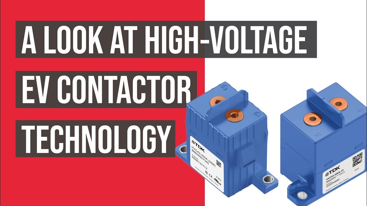
Xem video giáo dục trên YouTube.
Các câu hỏi thường gặp
What is the first rule for bess bidirectional contactor?
Xác định ranh giới của mạch và mọi nguồn có khả năng cung cấp năng lượng cho nó, sau đó xác minh chính xác hoạt động của thiết bị dựa trên các dạng sóng điện áp và dòng điện đã đo được.
Liệu thông tin phản hồi bổ sung có thể chứng minh rằng các liên hệ chính vẫn còn mở không?
Không. Phân tích mối tương quan giữa trạng thái phụ với điện áp bus, dòng điện chuỗi, dòng điện cuộn dây, thời gian và tất cả các đường dẫn hồi tiếp có thể xảy ra.
Liệu một contactor có nên thay thế cầu chì dây không?
Không. Bộ phận tiếp xúc cung cấp chức năng chuyển mạch có kiểm soát, trong khi cầu chì bảo vệ dòng điện quá tải. Nhiệm vụ chịu tải và ngắt dòng của chúng phải được phối hợp.
Dữ liệu nào nên được bao gồm trong yêu cầu cung cấp báo giá cho bộ phận tiếp xúc BESS?
Đưa vào phạm vi điện áp, dạng sóng dòng điện, chế độ làm việc bật/tắt, hướng dòng điện, tính năng sạc trước, dòng điện quá tải, bảo vệ, nhiệt độ, cách lắp đặt, điều khiển cuộn dây, phản hồi và mục tiêu tuổi thọ.
Các tài liệu tham khảo có thẩm quyền
- Tiêu chuẩn OSHA 1910.147 – Kiểm soát năng lượng nguy hiểm
- Tiêu chuẩn OSHA 1910.333 — Thực hành công việc điện
- IEC 60947-4-1 — Van cầu và bộ khởi động động cơ
- Bộ Năng lượng Hoa Kỳ — lưu trữ năng lượng
Hãy sử dụng các phiên bản và yêu cầu được thông qua trong dự án. Các tiêu chuẩn và thông số kỹ thuật có thể thay đổi, vì vậy nhóm kỹ thuật chịu trách nhiệm phải xác nhận thiết kế cuối cùng.





