Быстрый ответ: An 800V EV contactor must be selected for the battery’s maximum charged voltage and transients, not the nominal architecture label. It must also satisfy insulation coordination, DC make and break duty, bidirectional current, thermal rise, precharge, short-circuit coordination, coil-driver behavior, feedback diagnostics, environmental stress, and the vehicle’s required switching life.
Этот инженерный руководство превращает эту тему в последовательность шагов для команд по разработке аккумуляторных батарей, BMS, тестированию, закупкам и обслуживанию. В нем используется реальная линейка продукции в качестве основы, при этом все оценки и решения по безопасности связаны с конечной целью применения и текущими документами производителя.
Карта решений
| Оперативное состояние | Ожидаемые доказательства | Сфокусированность на инженерных разработках |
|---|---|---|
| Maximum working voltage | Highest charged pack plus defined operating tolerance | Use model-specific DC ratings and system transients |
| Insulation | Clearance, creepage, dielectric and pollution environment | Coordinate pack, enclosure, altitude and service access |
| Current duty | Traction, regeneration, charging and fault opening | Separate continuous, peak, make and break conditions |
| Защита | Fuse, pyrofuse, precharge and discharge coordination | Prove fault energy and safe isolation sequence |
Ссылка на продукт и границы его применения
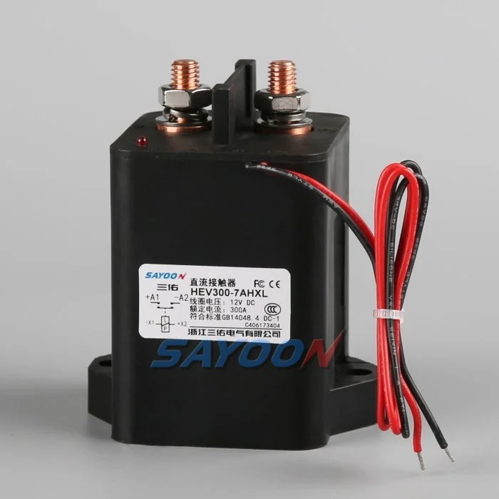
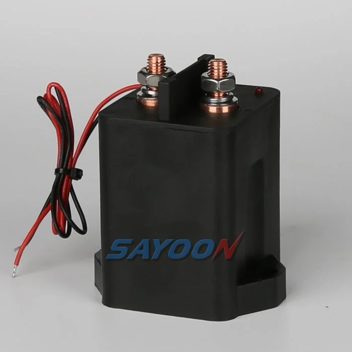
Эт HEV300 high-voltage sealed DC contactor На фото представлен настоящий образец продукции Sayoon. Проверьте сеть высоконапряжных контакторов постоянного тока для смежных классов токов. Изображение и название семейства не устанавливают одобрения для конкретного транспортного средства. Финальную цифру номера, вариант катушки, чертеж, электрическая нагрузка, изоляция, среда обитания, срок службы и согласование защиты необходимо рассматривать вместе.
800V is an architecture class, not one fixed voltage
An “800V” vehicle does not operate at exactly 800 V in every state. The pack voltage changes with cell chemistry, series count, state of charge, temperature, and load. Charging and regeneration can place the pack near its maximum charged voltage, while switching transients can briefly add stress. Specify the minimum, nominal, maximum continuous, and defined transient voltages.
Select the contactor using the manufacturer’s approved DC voltage conditions and insulation data. Do not approve a device merely because its name includes 800 V or because an AC insulation number looks high.
Insulation coordination and altitude
Higher voltage increases the importance of creepage, clearance, dielectric withstand, pollution degree, material group, sealing, and the distance to grounded metal. Altitude reduces air density and can require larger clearances or derating. The completed battery junction box—not the contactor alone—must maintain the required insulation under condensation, contamination, vibration, and service conditions.
Review terminal spacing, busbar geometry, mounting hardware, sensors, connector pins, and enclosure ribs. Use the standards and vehicle requirements adopted by the project; do not copy a spacing number without matching the environment and overvoltage category.
DC interruption at higher voltage
A DC arc does not naturally cross zero. At higher voltage, the contactor’s arc-control system, contact gap, opening speed, magnetic field, gas sealing, and current direction become critical. Continuous current and breaking current are different ratings. Confirm make and break performance at the maximum voltage, actual load inductance, and the required polarity or bidirectional condition.
Normal control should reduce inverter or charger current before opening when safe. Emergency opening, crash isolation, and fault interruption require separately qualified duties and protection coordination.
Thermal current and power relationships
For the same power, higher voltage can reduce current, but that does not automatically make the contactor cooler. Fast charging, launch, regeneration, enclosure temperature, terminal resistance, and busbar design still determine heating. Contact loss is approximately I²R, and joint resistance outside the contactor can become equally important.
Use measured current profiles and thermal boundary conditions. Verify temperature rise at the terminals and body with the production busbar, torque, conductor size, airflow, and neighboring fuse or pyrofuse.
Precharge and discharge
The inverter DC link must be charged through a controlled path before the main contactor closes. At 800V-class levels, the stored energy and make-current consequence are substantial. Size the resistor and precharge contactor for maximum voltage difference, capacitance, pulse energy, repeat duty, and temperature. Close the main contactor only after measured voltages meet the approved ratio and timing window.
After opening, verify that the discharge circuit reduces the load-side bus to the vehicle-defined safe threshold. A timer without voltage confirmation cannot prove the bus is safe.
Bidirectional current and charging compatibility
Traction current flows from the battery to the inverter, while regeneration and DC charging send current toward the battery. Confirm that the main contactor carries and switches the required directions. Some 800V vehicles also interact with lower-voltage chargers through a booster or reconfiguration strategy, which can create additional contactor states and switching sequences.
Map each configuration and prevent two contactors from creating an unintended parallel or series path. Add feedback and bus-voltage plausibility checks for every state.
Short-circuit and crash coordination
Define the prospective pack fault current, battery impedance, cable and busbar inductance, fuse or pyrofuse clearing behavior, and the contactor’s required withstand or interruption duty. The contactor is not a substitute for a fuse, and a fuse does not provide repeatable functional switching. The safety concept should state which device acts first and what energy remains downstream.
After a crash event, inhibit reclose, verify isolation and discharge, and require inspection of the contactor, terminals, busbars, fuse, precharge branch, and trigger circuits before service release.
Coil drive, feedback and EMC
The low-voltage coil driver must provide reliable pull-in during supply sag and controlled release during faults. Suppression changes opening time and driver stress. Capture coil current, command, auxiliary feedback, pack voltage, and load-side voltage on one time base. Use independent voltage evidence to detect welded or stuck-open main contacts.
At 800V-class switching levels, layout, shielding, grounding, and measurement isolation affect EMC and diagnostic accuracy. Validate the production harness and controller, not only a short bench setup.
RFQ and qualification checklist
Provide minimum, nominal, maximum and transient pack voltage; continuous and peak currents; current direction; make and break waveforms; DC-link capacitance; precharge and discharge requirements; short-circuit source; protection clearing time; insulation environment; altitude; temperature; vibration; sealing; coil voltage; driver and suppression; auxiliary logic; life; mounting; busbars; and required approvals.
The HEV300 shown here is a product reference. Confirm the exact voltage, current, insulation, coil, and endurance data for the final model and production installation.
Документы о признании
Создайте один управляемый регистр, содержащий полную информацию о номере детали, версии чертежа, опции для катушек, функциональных возможностях терминала, диапазоне напряжения, форме тока, состоянии переключения, деталях предварительного заряда и разряда, драйвере и подавном устройстве, вспомогательной логике, состоянии HVIL, защите, температуре окружающей среды и корпуса, ориентации крепления, деталях проводника и распределительной шины, местоположения приборов, статусе калибровки, версии программного обеспечения и ограничениях пропуска/отрицания. Отдельно отслеживайте измеренные значения от значений из каталога и укажите отсутствующие данные как открытую задачу, а не вставляйте типичное значение.
Проверьте те параметры, которые имеют значение: низкое и высокое напряжение в цепи питания, условия холода и тепла, максимальная разрешенная длина шнура, повторные циклы и ненормальное состояние, указанное в концепции безопасности. Запишите данные о команде остановки, напряжении и токе в цепи питания, вспомогательной обратной связи, напряжении в аккумуляторной батарее, напряжении в нагрузке и проблемах с показателями на одном таймере. Прекратите автоматические повторные попытки после неполадок, вызванных необъяснимыми обстоятельствами, изолируйте накопленную энергию и сохраните данные о первых проблемах. Сфотографируйте схему установки и расположение выводов, идентифицируйте все точки зонда, запишите схему аккумуляторной батареи и распределительную шину и объясните, почему каждый порог является безопасным. После термостабилизации и после запланированного периода испытаний повторите испытание на репрезентативной выборке. Включите оператора, дату испытания, идентификацию образца, а также любые отклонения от утвержденного набора. После последующего успешного испытания не следует стереть предыдущую ошибку. Эти данные позволяют сравнить новый образец с ранее зарегистрированными данными, а также с исходным набором данных, разработанным поставщиком.
Also verify labeling, service documentation, isolation points, and change-control approvals before the production design is released to vehicle assembly.
Связанные статьи Сайун
Используйте Руководство по выбору контакторов постоянного тока, безопасный рабочий процесс проверки контактора, и Руководство по времени открытия и закрытия для принятия дополнительных решений. feedback plausibility guide explains command, auxiliary, and bus-voltage correlation.
Обучающее видео
WHAT IS 800-Volt Architecture in EVs? by EV Zone provides visual background related to this engineering review. It does not replace the written requirements, product data, or vehicle safety procedure.
Посмотрите обучающее видео на YouTube.
Часто задаваемые вопросы
What is the most important check for 800v ev contactor?
Начните с максимального напряжения и реального импульса переключения, а затем проверите точность данных контактора, последовательность управления, установку и поведение при неисправности вместе.
Может ли вспомогательный контакт подтвердить, что основные контакты здоровы?
Нет. Механизм отчетности о вспомогательной подаче обратной связи работает в рамках своих ограничений. В качестве независимых факторов используются напряжение на шине, время срабатывания, ток на катушке и состояние схемы.
Можно ли использовать номинальный ток в качестве основного критерия выбора?
Нет. Постоянный ток, малый ток, перепад напряжения, температура, полярность, срок службы, изоляция и координация защиты — это отдельные условия.
Какие сведения следует включать в запросе о закупке?
Отправьте данные о токовом и напряжённом токах, последовательности переключений, условиях эксплуатации, характеристиках катушки и драйвера, логике обратной связи, защите, монтаже, целевом сроке службы и требуемых испытательных данных.
Авторитетные источники
- SAE J1766 electric and hybrid vehicle safety practice
- Компания Texas Instruments использует высоконапряженные контакторы для электромобилей и гибридных транспортных средств
- NHTSA electric-vehicle safety information
- Berkeley power electronics technical report
Используйте версию и требования, утвержденные программой автомобиля. Стандарты и данные поставщика могут измениться, и ответственная инженерная команда должна подтвердить окончательный проект.





