An HV contactor on an EV battery disconnect path must be chosen for maximum pack voltage with headroom, the continuous current of the connected path, the planned switching duty, and coordination with precharge sequencing and BMS feedback — not from a single ampere label on a datasheet.
This guide is for OEM engineers and BDU integrators who need a specification record that procurement and electrical safety reviewers can audit. For market context on electrification demand, see the site’s e-mobility and energy storage trends. Browse SEV Series HV DC contactors when you are ready to compare published SKUs.
Contents
- Part 1. What does an HV contactor decide in the battery disconnect path?
- Part 2. Which inputs must be defined before specifying an HV contactor?
- Part 3. How should teams set voltage class and headroom?
- Part 4. How do continuous current, duty cycle, and interrupt capability interact?
- Part 5. What coil, auxiliary, and economizer choices matter for BMS integration?
- Part 6. Which RFQ fields help OEM teams validate an HV contactor shortlist?
- Part 7. What common mistakes appear in EV disconnect-path specifications?
Part 1. What does an HV contactor decide in the battery disconnect path?
The HV contactor decides whether the pack can be galvanically connected to or isolated from the traction inverter, charger inlet, or auxiliary DC bus under normal commands and fault-driven opens. In a typical battery disconnect unit (BDU), main contactors are the controlled switches the battery management system (BMS) commands after interlocks and precharge conditions are satisfied.
Readers searching hv contactor are usually past the definition stage. They need to know which electrical and control fields belong on a disconnect-path specification before a part number is frozen. That is different from choosing a low-voltage coil relay for an accessory circuit, covered separately in the contactor versus relay differences article.
| BDU element | Primary role | Typical control owner |
|---|---|---|
| Main HV contactor(s) | Connect/disconnect main current path | BMS / vehicle supervisor |
| Precharge path | Limit inrush onto capacitive DC link | BMS timed sequence |
| Auxiliary contacts | Report contact state to control logic | BMS input |
| Fuses or pyro devices | Address short-circuit energy | Protection study |
The high-voltage system overview at BatteryDesign.net describes main contactors as normally open so the path de-energises when control power or logic removes the hold command. Treat that as an architecture expectation to verify on your schematic, not as a substitute for your platform’s safety case.
Part 2. Which inputs must be defined before specifying an HV contactor?
Freeze the inputs that appear on the BDU drawing set and the component specification sheet. Without them, two suppliers can both quote “400 A” yet be incompatible with your bus voltage, precharge sequence, or feedback logic.
Input checklist
| Input | Why it matters | Example record field |
|---|---|---|
| Maximum pack/working voltage | Sets contact voltage class | 400 V nominal, 920 V max during charge |
| Continuous current on closed path | Sets thermal current class | 320 A drive, 180 A charge |
| Peak or surge duration | Tests thermal inertia | 450 A for 30 s acceleration profile |
| Switching operations per day | Drives electrical life target | 15 cycles/day service disconnect |
| Precharge bus capacitance | Sets inrush and sequencing | 2 mF DC link, 2 s precharge target |
| Coil control voltage | Matches BMS output | 24 VDC hold, economizer after pull-in |
| Auxiliary contact requirement | State feedback to BMS | 1 NO auxiliary for main state |
| Ambient and enclosure class | Derating and sealing | IP67 BDU, −30 °C to 55 °C |
Forum and integrator discussions repeatedly ask whether precharge must complete before mains close. Document the voltage threshold and timeout on the sequence chart so assembly and validation teams share one source of truth.
Part 3. How should teams set voltage class and headroom?
Contact voltage rating must cover the highest sustained potential the contacts see in service, including charge tolerance and transient conditions your platform defines. Use the platform maximum, then add the headroom your safety process requires; do not assume a nominal pack voltage alone is sufficient.

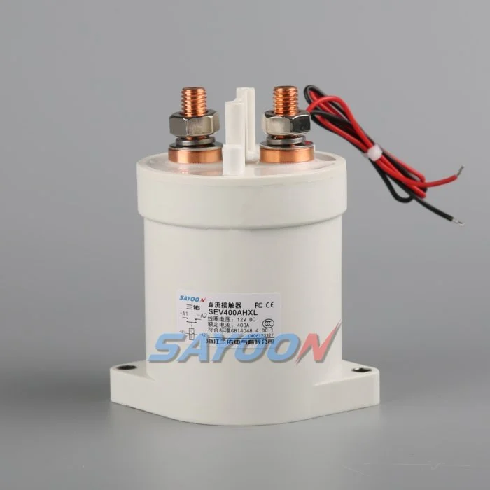
Published SAYOON SEV400AH parameters list contact voltage (DC V) 5–1000 V and 400 A DC-1 continuous load current under the stated test conditions on the product page. Use those fields only when your working voltage and current fall within the documented test context. If your platform exceeds published bounds, escalate to engineering review rather than extrapolating.
| Planning question | Documented answer location | Common gap |
|---|---|---|
| Nominal vs maximum pack voltage | BMS limits / cell map | Using nominal only |
| Where precharge is measured | BDU schematic | Measuring at wrong node |
| Is redundancy required? | Platform safety concept | Single pole without analysis |
| Service disconnect operations | O&M manual | Ignoring maintenance cycling |
Standards families such as ISO 6469 address road-vehicle electrical safety at the system level. They inform what your safety file must discuss; they do not, by themselves, prove that any one contactor SKU is approved for your vehicle category.
Part 4. How do continuous current, duty cycle, and interrupt capability interact?
Continuous current class addresses thermal steady state while the path is closed. Duty cycle captures how often the contactor switches under load. Interrupt or rupture capability addresses what the contact path can open under defined fault energy — a separate question from everyday driving current.
Specification sequence
- Record continuous current at the contactor node for each drive/charge mode you support.
- Add duty-cycle context: operations per trip, per day, and any service disconnect routine.
- Identify whether the contactor must open under load, only after current falls, or only with upstream protection clearing energy.
- Compare candidate devices using the supplier’s published rupture or fault-current fields at your working voltage — not at a generic table voltage.
- Cross-check against high-current path articles such as high-current BESS path sizing context only when your architecture truly shares those current magnitudes.
On the published SEV400AH page, typical fault currents which can be ruptured are listed as 1500 A / 5 ms at 48 V DC under the supplier’s stated test conditions. Do not transfer that rupture field to a different voltage or time constant without supplier confirmation.
| Rating type | Answers | Does not answer |
|---|---|---|
| Continuous current (DC-1) | Thermal carry while closed | Short-circuit energy alone |
| Electrical life (cycles) | Contact wear under defined switching | Unlimited fault openings |
| Rupture field | Limited fault event at stated voltage/time | All platform fault scenarios |
Part 5. What coil, auxiliary, and economizer choices matter for BMS integration?
Coil voltage, pull-in/drop-out thresholds, and economizer behaviour determine whether the BMS output driver can reliably hold the contactor without overheating the coil. Auxiliary contacts provide position feedback so control logic does not assume state from coil voltage alone.
Published SEV400AH coil data includes multiple DC coil options (for example 6 V through 150 V classes on the product page), pull-in at ≯70% and drop-out between ≯35% and ≮5% of rated coil voltage at (20±5) °C, and economizer-style hold power listed as H: Start 30–60 W, Keep 4–10 W under the published table. Map those values to your driver capacity and temperature corners.
Integrators often specify:
- Polarity and suppression on the coil driver to protect BMS outputs
- Auxiliary contact rating relative to sense current (published optional auxiliary example: 3 A / 30 VDC on SEV400AH page)
- Economizer engagement timing so pull-in is not truncated
If your platform needs latching or magnetic holding behaviour for hold-power savings, that is a different coil class than standard economizer designs — confirm on the model implication chart before reuse.
Part 6. Which RFQ fields help OEM teams validate an HV contactor shortlist?
Use a single RFQ table so sales and application engineering can respond with a comparable datasheet, 3D step, and coil variant.
RFQ input list
| RFQ field | Buyer provides | Supplier returns |
|---|---|---|
| Platform / BDU drawing | Single-line snippet | Mounting footprint |
| Voltage class | Max working DC voltage | Contact voltage rating |
| Continuous current | Per mode table | DC-1 rated current |
| Switching duty | Cycles/day, load class | Electrical life estimate |
| Fault coordination | Upstream fuse/py ro curve | Rupture capability at voltage |
| Coil control | Voltage, PWM?, suppression | Coil code and consumption |
| Auxiliaries | NO/NC count | Auxiliary rating |
| Environment | IP, temperature, vibration | Derating statement |
| Certifications needed | Target markets | CE/RoHS/FCC scope per model |
Fit Boundary
- Suitable when your documented voltage and continuous current fit inside published SAYOON SEV parameters, precharge is implemented separately, and BMS feedback wiring matches auxiliary options.
- Not suitable when you need system-level vehicle or grid-code compliance evidence from the contactor datasheet alone, or when fault energy at pack voltage exceeds supplier-confirmed rupture data.
- Confirm first maximum voltage during charge, precharge finish threshold, and whether mains open under load or only after current decay.
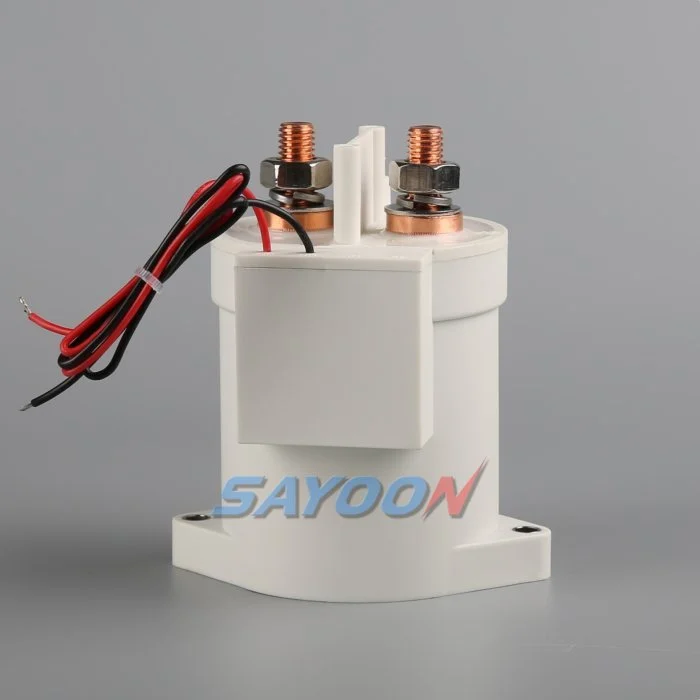
For application context on vehicle programmes, review new energy electric vehicle applications and compare candidate SKUs such as the SEV400AH high-voltage DC contactor against your RFQ table. Send BDU drawings and voltage class when you need coil variant and auxiliary confirmation.
Part 7. What common mistakes appear in EV disconnect-path specifications?
Mistake 1 — Rating from nominal voltage only. Charge and regeneration corners can sit above nominal pack voltage. Specification sheets should list maximum working voltage, not marketing nominal only.
Mistake 2 — Ignoring precharge in the same BOM line as mains. Main contactor current rating does not replace a precharge resistor, timer, and sense strategy.
Mistake 3 — Assuming rupture data transfers across voltage. A fault rupture field published at one voltage/time pair is not automatic proof at your pack voltage without supplier validation.
Mistake 4 — Feedback from coil voltage only. Auxiliary contacts or validated position sensing should align with functional safety or OBD expectations defined by your platform.
Mistake 5 — Reusing amp-only blog conclusions for HV class. Articles focused on 100 A or 1000 A paths address current magnitude; they do not replace voltage class and BDU sequencing for HV disconnect paths.
FAQ
What is an HV contactor in an electric vehicle?
It is a controlled high-voltage DC switch, typically normally open, that connects or isolates the battery pack from the traction or distribution path under BMS command.
How do main contactors work in a battery disconnect unit?
The BMS energises coils after interlocks and precharge conditions pass, closes the main path for operation, and opens coils on shutdown or fault to de-energise the path.
Why is precharge required before closing HV contactors?
Precharge limits inrush current into capacitive loads such as inverter DC links, reducing contact welding risk and voltage stress during initial closure.
What voltage rating should a DC contactor have for an 800 V class pack?
It must meet or exceed the maximum working voltage your platform defines for that path, including charge and transient conditions, with the headroom your safety process requires — verified against supplier data.
What is the difference between an HV contactor and a relay in EV systems?
Contactors are built for higher DC carry and switching duty in power paths; relays typically serve lower-power control circuits. See the dedicated comparison article for 24 V control contexts.
Which certifications should appear on an RFQ for export programmes?
List target markets and required marks (for example CE, RoHS, FCC) and ask suppliers to map scope to the exact model and test report — not a corporate-level statement alone.
When should engineering escalate beyond catalog selection?
When fault energy, redundancy, or temperature corners exceed published tables, or when platform safety case requires evidence not present on the public product page.
References
- BatteryDesign.net — High Voltage System — BDU elements and normally open contactor practice
- EVolve Library — High-Voltage Battery Architecture — HV safety architecture framing
- ISO 6469-3 — Electrically propelled road vehicles — System-level electrical safety standard family (context)
- BSB Electric — DC Contactor Selection Guide — Industry selection factors for HV DC classes





