An EV contactor on traction or main pack paths must be specified for pack-voltage class, fault-energy context, duty, sealing, and BMS feedback, while many auxiliary circuits can use standard DC contactor classes only when contact potential, current, and duty are lower and documented — not because the vehicle is electric.
This comparison is for OEM engineers and BDU integrators who must decide whether traction disconnect, charge path, and auxiliary loads can share one contactor catalog line. For disconnect-path field detail, see HV contactor selection for EV battery disconnect. Review new energy electric vehicle applications on SAYOON’s site for programme-level positioning.
Part 1. What do buyers mean by EV contactor versus standard DC contactor?
Buyers use EV contactor for devices qualified on pack-voltage mains, charge paths, or other high-potential DC buses where rupture data, sealing, and BMS feedback matter. Standard DC contactor usually means industrial or mobility classes sized for lower potential branches — forklift traction at 48 V, distribution at 72 V, or control-heavy auxiliaries — not necessarily pack-level HV.
The label on the marketing page does not replace circuit analysis. A contactor is “for EV” only when your documented contact voltage, duty, rupture context, and environmental class match the path it switches.
| Term in RFQ | Usually implies | Still requires |
|---|---|---|
| EV contactor | Pack-voltage main or charge path | Test voltage on rupture line |
| Standard DC contactor | Lower-potential industrial/mobility branch | Contact voltage ≥ circuit maximum |
| Traction contactor | Drive inverter feed or main disconnect | Fault-energy coordination |
| Auxiliary contactor | HVAC, pumps, DCDC input, heaters | Actual net voltage and duty |
Low-voltage control discussions belong in low-voltage contactor versus relay differences, not in pack-main specifications.
Part 2. What does a traction or main pack path require from an EV contactor?
Traction and main pack paths see the highest sustained potential on the vehicle DC system. Contactors here must be audited for contact voltage class with headroom, continuous current under real drive and charge modes, limited fault-opening capability at stated test conditions, and position feedback the BMS treats as safety-relevant.
The high-voltage system overview at BatteryDesign.net describes main contactors as normally open elements the BMS commands after interlocks and precharge — architecture language your schematic should mirror.
Traction-path minimum evidence
- Maximum working contact voltage on the switched net
- Continuous current per operating mode (drive, regen, charge)
- Switching operations per day and service disconnect routine
- Rupture or interrupt field with voltage, time, and method reference
- IP or sealing class for the BDU location
- Auxiliary contact rating for state feedback
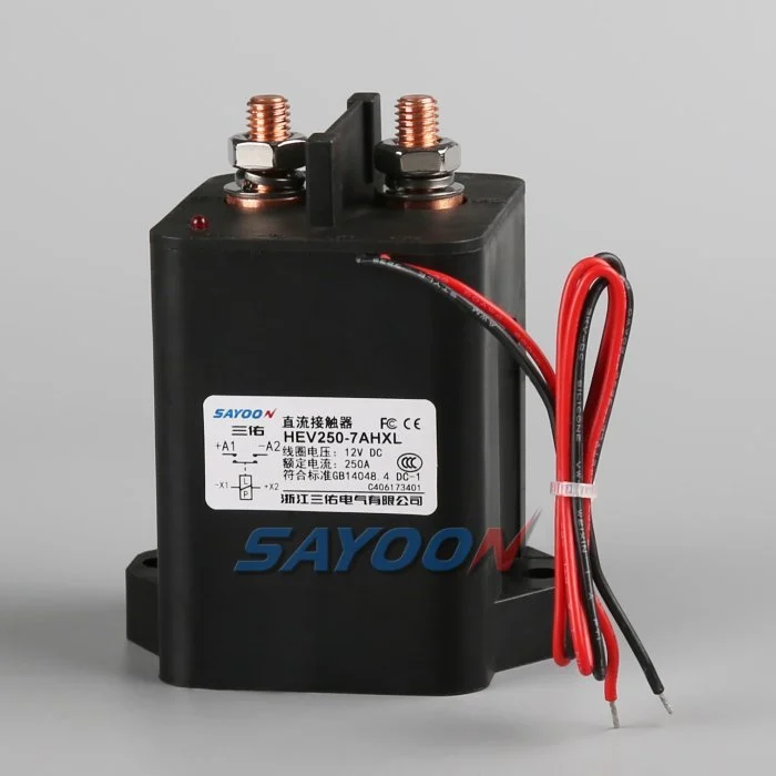
Published SAYOON HEV250 parameters should be quoted only from the live product table when your RFQ fits that SKU envelope. Browse HEV Series HV DC contactors for additional HV mobility options.
Part 3. When can a standard DC contactor serve auxiliary EV circuits?
Auxiliary circuits — cabin HVAC compressors, coolant pumps, heaters, or downstream DCDC inputs — may sit at lower potential if your architecture isolates them. A standard DC contactor class can be appropriate when the switched net’s maximum voltage, continuous current, switching duty, and environmental exposure are documented and fall within the supplier’s published bounds.
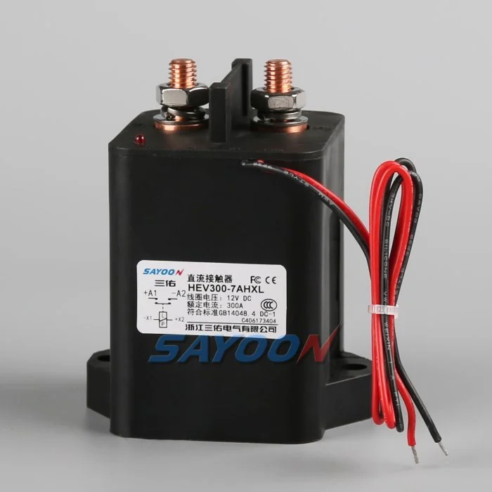
That is not permission to place a 48 V industrial class device on a pack main. The 48 V DC contactor application context article explains where lower-voltage classes fit material-handling and light traction — useful when your aux branch truly operates in that class.
| Circuit role | Often lower potential? | Typical contactor class | Verification gate |
|---|---|---|---|
| Pack main / traction feed | No | EV / HV DC | Rupture + BMS feedback |
| Fast-charge inlet path | Usually pack class | EV / HV DC | Coordination with charge control |
| DCDC input from pack | Pack or intermediate | HV or qualified intermediate | Schematic net voltage |
| Post-DCDC aux branch | Sometimes yes | Standard DC if voltage fits | Net maximum and duty |
| 12 V control branch | Yes | Relay or small DC contactor | Not a pack main substitute |
Any “yes” in the lower-potential column still needs a single-line diagram node name and measured maximum.
Part 4. How do voltage class and sealing requirements diverge between paths?
Pack-voltage paths stress contact gap, insulation, and enclosure sealing differently than aux branches mounted in cabin or engine-compartment sub-enclosures. EV contactor specifications therefore emphasize contact voltage class, epoxy or hermetic sealing, and IP ratings suited to road splash, wash, or vibration.
Auxiliary branches may see milder exposure yet still require sealed devices when mounted in humid zones. Do not downgrade IP class without locating the device on the vehicle layout drawing.
| Factor | Traction / pack main | Many auxiliary branches |
|---|---|---|
| Contact voltage class | Pack maximum + headroom | Actual switched net maximum |
| Sealing | Often IP6x / epoxy sealed HV types | May accept lower IP if location permits |
| Vibration | Road load, inverter proximity | Depends on mounting |
| Service access | Safety-critical disconnect | May allow different maintenance cycle |
Environmental assumptions belong in the RFQ packet, not in informal email footnotes.
Part 5. How do control, feedback, and duty differ between traction and aux?
Traction contactors switch less frequently than many industrial motor branches but carry higher stakes when they open under load or during fault routines. Auxiliary contactors may cycle more often at lower current, yet still need coil and auxiliary ratings matched to the supervising controller.
Control differences to document
- Coil voltage and peak hold power on the driver
- Economizer timing relative to BMS output capability
- Auxiliary contact configuration for traction versus simple ON/OFF aux loads
- Debounce and timeout logic on feedback inputs
- Whether traction paths require redundant poles or parallel monitoring
Forum discussions often ask whether one SKU can serve traction and aux to save tooled housings. Cost savings are valid only after both paths pass independent voltage, duty, and feedback audits.
Part 6. What decision table helps OEM teams split traction and auxiliary contactors?
Use one matrix per vehicle programme before freezing part numbers.
| Question | Traction / pack main | Auxiliary branch | Same SKU allowed? |
|---|---|---|---|
| Maximum contact potential | (fill) | (fill) | Only if both ≥ required class |
| Continuous current | (fill) | (fill) | Only if thermal class fits both |
| Rupture / fault context | (fill) | (fill) | Usually no if aux lacks rupture data |
| BMS safety feedback required? | Typically yes | Sometimes yes | Depends on logic |
| IP / sealing class | (fill) | (fill) | Compare separately |
| Electrical life vs duty | (fill) | (fill) | Higher duty path governs |
When traction needs HV class, start RFQ review on HEV Series HV DC contactors and cite published parameters on candidates such as the HEV250 high-voltage DC contactor. When aux paths remain in lower industrial classes, document that choice explicitly so procurement does not copy the traction part number by habit.
Fit Boundary: Series marketing scope does not replace per-circuit voltage and duty proof. Platform safety files may require additional test evidence beyond catalog pages.
Part 7. What misapplications appear when one contactor class is reused everywhere?
Common misapplications on EV programmes
- Forklift-class 48 V device on pack main — contact voltage and rupture lines cannot support pack potential.
- Traction HV device on 12 V control branch — oversized coil demand and wasted envelope.
- Aux duty assumed negligible on mains — maintenance cycling wears mains faster than steady-state thermal calcs suggest.
- Missing auxiliary feedback on traction — BMS validation fails despite correct coil voltage.
- Single PO line for “EV contactor” without circuit name — supplier ships a valid SKU for the wrong net.
When traction and auxiliary requirements diverge, send traction and auxiliary circuit drawings for series confirmation instead of forcing one catalog row across all loads.
References
- BatteryDesign.net — High Voltage System — traction versus system architecture
- EVolve Library — HV Battery Architecture — main contactor role context
- ISO 6469-3 scope (road vehicles — electrical safety) — system-level electrical safety context
FAQ
What is an EV contactor?
In OEM usage, an EV contactor is a DC contactor specified for pack-voltage or other high-potential vehicle paths where contact voltage class, rupture context, sealing, and BMS feedback are documented — not merely any contactor installed on an electric vehicle.
Can a standard DC contactor be used on an electric vehicle?
Yes on auxiliary or lower-potential branches when the switched net’s maximum voltage, current, duty, and environment fit the supplier’s published class. No on pack mains or traction feeds without HV-class evidence equivalent to your platform requirements.
What is the difference between traction and auxiliary contactors on EVs?
Traction or main paths carry pack-level potential and usually require HV-class rupture data and safety-related feedback. Auxiliary paths may operate at lower potential with different duty and environmental exposure, allowing standard DC classes when documented.
Do auxiliary EV circuits need high voltage contactors?
Only when the auxiliary net’s maximum contact potential and duty require HV class. Post-DCDC or isolated low-voltage branches may use standard DC contactor classes after schematic verification.
When should engineers use separate contactors for traction and aux loads?
When voltage class, rupture context, duty, sealing, or feedback requirements differ enough that one published SKU cannot cover both paths with auditable evidence. Use the decision table in Part 6 before sharing part numbers across circuits.
How does coil demand differ between traction and aux paths?
Traction mains often use economizer coils with higher pull-in power and safety-rated auxiliary feedback. Auxiliary branches may use simpler coil profiles but still need driver sizing from published peak and hold watts.
Which SAYOON series should RFQ name first for EV traction?
Start with HEV or SEV HV DC contactor series pages for pack-voltage paths, then down-select using published SKU tables. Name lower-voltage CZW or SZJ series only when the auxiliary single-line proves lower contact potential and duty.





