Un contactor previo en el vocabulario de vehículos eléctricos es el contactor de precarga: un pequeño contactor sellado de CC de alta tensión que se cierra primero a través de una ruta de precarga para que la capacitancia del enlace de CC se cargue bajo corriente controlada, y solo entonces se cierra el principal, lo que limita la corriente de irrupción que de otro modo erosionaría o soldaría los contactos principales, con elecciones de dispositivos auditadas frente a campos de series HEV publicados.
Este artículo explicativo está dirigido a ingenieros de tren motriz y BMS de vehículos eléctricos que heredaron el término de las listas de proveedores y necesitan relacionarlo con el diseño de precarga real. La familia de dispositivos detrás de este término en este sitio es el Contactores de CC de alta tensión de la serie HEV línea, y cada afirmación de modelo a continuación cita una fila de tabla publicada.
Parte 1. ¿Qué significa contactor de precarga en el vocabulario de precarga de vehículos eléctricos?
La frase precontacto magnético aparece en las listas de palabras de los proveedores y en los catálogos traducidos, y confunde a los equipos porque magnético también describe las arquitecturas de enclavamiento. En el contexto de precarga, el mapeo es simple: es el contactor de precarga, el contactor pequeño que conduce primero, antes de la ruta principal.
SAYOON publica ese mapeo en las páginas de su aplicación, donde los contactores de precarga se enumeran para el control de precarga antes de la conexión del circuito principal. Así que trate el término como un nombre de función en la secuencia de conexión, no como una tecnología de dispositivo separada.
| Término visto en listas | Función en el circuito del vehículo eléctrico | Donde se publica |
|---|---|---|
| Contactor pre-magnético / de precarga | Se cierra primero a través de una ruta de resistencia para cargar el enlace de CC | Mapeo de productos en páginas de soluciones |
| Contactor principal | Transporta la corriente de tracción o del autobús después de la carga | SKUs de la ruta principal HEV / SEV |
| Contactor magnético de enclavamiento | Arquitectura de ahorro de energía en espera, un tema diferente | Páginas de la familia CZW-K |
Parte 2. ¿Por qué la corriente de irrupción impulsa el diseño de precarga en los enlaces de CC de los vehículos eléctricos?
Los circuitos de entrada de los inversores presentan grandes capacitancias descargadas a la batería en el momento de la conexión. Cerrar un contactor directamente sobre esa carga genera un pico de corriente limitado principalmente por la resistencia del bucle: el clásico fenómeno capacitivo. corriente de entrada problema.
Los relatos de campo repiten la consecuencia: contactos principales erosionados o soldados después de repetidas conexiones bruscas. Una rama de precarga mitiga el pico cargando primero el enlace a través de una resistencia, de modo que el contactor principal se cierra con una pequeña diferencia de voltaje en lugar de un condensador descargado.
| Hecho de diseño | Consecuencia sin cargo previo | Respuesta de precarga |
|---|---|---|
| El enlace de CC comienza descargado | Conectores de pines de alta presión | Enlace de carga antes del cierre principal |
| Pico limitado únicamente por la resistencia de bucle | Erosión, soldadura, fallas molestas | Corriente de carga limitada por resistencia |
| Conexiones repetidas por día | Daño por contacto acumulativo | Secuencia controlada y repetible |
Parte 3. ¿Cómo funciona un contactor de precarga junto al contactor principal?
El patrón de trabajo es una secuencia de tres pasos gestionada por el BMS o el controlador del vehículo. Los detalles del orden de los pasos se cubren en directo conceptos básicos de la secuencia de conexión de precarga y principal guía, para que este artículo mantenga la vista del dispositivo.
- Cierre el contactor principal negativo y el contactor de precarga; la corriente fluye a través de la resistencia de precarga.
- Monitoree el voltaje del enlace hasta que se cumpla el criterio de carga del controlador.
- Cierre el contactor principal positivo, luego abra la rama de precarga, la cual vuelve a reposo.
Se siguen dos consecuencias para los dispositivos. El contactor de precarga experimenta una corriente menor limitada por resistencia, pero debe coincidir con la clase de voltaje del bus, y acumula una operación por ciclo de conexión, por lo que sus filas de vida útil publicadas importan tanto como su línea de corriente. La función distinta de los dispositivos principales se compara en Contactor para vehículos eléctricos (EV) frente a contactor de corriente continua (DC) estándar.
Parte 4. ¿Qué campos de HEV publicados importan para el servicio de precarga y corriente de entrada?
El sistema de códigos HEV publica las clases de voltaje nominal de contacto de 1 -200V; 7 -1000V, que es el primer campo que debe coincidir con el bus. Más allá de eso, las clases pequeña y mediana publican las filas de las auditorías de diseño de precarga.
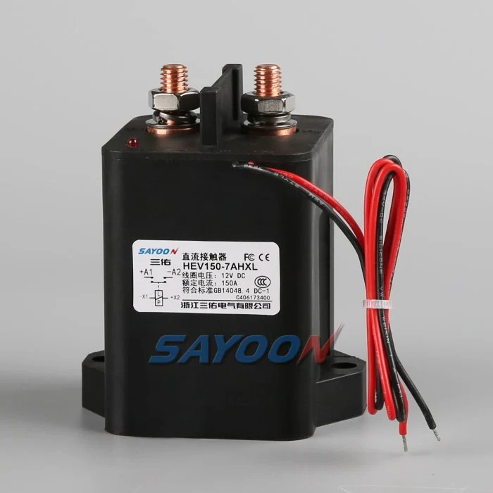
| Campo publicado | HEV30 | HEV100 | HEV150 |
|---|---|---|---|
| Clases de tensión de contacto | 200 V, 1000 V | 200 V, 1000 V | 200 V, 1000 V |
| Carga actual (CC-1) | 30 A | 100 A | 150 A |
| Línea de alimentación de la bobina | D: 3–7; H: Inicio 3–7, Mantener 0,5–1,5 | D: 4–10; H: Inicio 4–10, Mantener 0,5–2 | D: 4–10; H: Inicio 4–10, Mantener 0,5–2 |
| Tiempo de corriente de entrada (máx.) | 130 ms | 130 ms | 130 ms |
| Protección / ambiente | IP68 / -40 a +85 °C | IP68 / -40 a +85 °C | IP68 / -40 a +85 °C |
| Vida eléctrica / mecánica | 20.000 / 300.000 veces | 20.000 / 300.000 veces | 20.000 / 300.000 veces |
Lea la fila del tiempo de irrupción como un límite de dispositivo publicado para ventanas de corriente anormal, no como una licencia para omitir la resistencia. El perfil de carga en sí es un cálculo del sistema propiedad del diseñador.
Parte 5. ¿Qué códigos de opción se relacionan con la precarga y las cargas capacitivas?
Las tablas publicadas de implicación de modelos contienen dos códigos de opción que vale la pena conocer en el trabajo de precarga. Son líneas de código, no componentes dimensionados, por lo que deben citarse únicamente como vocabulario de pedido.
| Código de opción publicado | Donde aparece | Lo que dice la página |
|---|---|---|
| R | tablas de códigos de la familia CZW | Con resistencia precargada |
| V | Tablas de códigos HEV / SEV | Con carga de tipo capacitivo |
| N | Tablas de códigos HEV / SEV | Sin polaridad |
La disciplina de pedidos se aplica de la siguiente manera: si un diseño asume cualquiera de esas opciones, la solicitud de cotización (RFQ) debe detallar el código completo y pedir a ingeniería que confirme la configuración entregada, debido a que las tablas públicas enumeran los códigos sin valores de resistencia ni límites de capacitancia.
Parte 6. ¿Qué modelos de SAYOON anclan una RFQ de precarga bajo el pilar HEV?
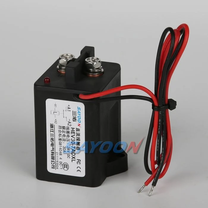
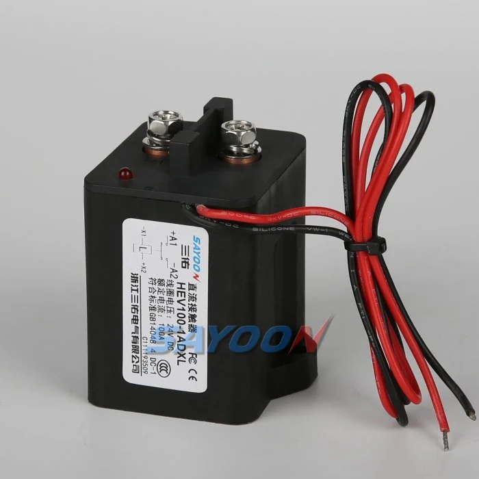
Recomendación de producto: anclar la rama de precarga en el Contactor de CC sellado con resina epoxi de alto voltaje HEV30 cuando la derivación se ajusta a su clase DC-1 de 30 A publicada y el bus coincide con un código publicado de 200 V o 1000 V. Emparéjelo con un dispositivo de la ruta principal como el Contactor de CC sellado con resina epoxi de alto voltaje HEV100 auditado en sus propias filas.
¿Por qué no otras líneas sin revisión? Las clases HEV150 y superiores pertenecen a las rutas principales, no a las ramas de precarga, en la mayoría de las arquitecturas; los códigos SEV son adecuados para programas estandarizados en esa familia; y no se debe asumir que ninguna SKU contiene una resistencia de más precarga interna que la indicada en su línea de código de opción publicada.
Ajustar Límite un contactor de precarga no es un dispositivo de tracción principal, ni un reemplazo para una resistencia de precarga correctamente diseñada, y no es válido fuera de su clase de voltaje publicada y filas de corriente. La lógica de selección de ruta de desconexión más amplia se encuentra en Selección de contactor de alta tensión para desconexión de batería.
Para confirmar una vinculación, envía tus notas sobre el enlace de CC y la precarga con la clase de voltaje del bus, capacitancia, corriente de rama y preferencias de bobina.
Parte 7. ¿Qué errores de diseño de precarga dañan las rutas de CC de los vehículos eléctricos?
- Omitir por completo la rama de precarga y conectar directamente el contactor principal a un enlace descargado.
- Elegir el dispositivo de precarga solo por la corriente y pasar por alto el código de clase de 200 V frente a 1000 V.
- Asumiendo que un código de contactor con la opción R define los ohmios y vatios de la resistencia — las tablas publican el código, no los valores.
- Ignorando los dispositivos de precarga del conteo de operaciones que se acumulan en cada ciclo de conexión.
- Tratar la fila de tiempo de corriente de conexión publicada como permiso para quitar la resistencia.
- Dejar la rama de precarga cerrada en paralelo con la ruta principal después de la conexión.
- Reutilizar el vocabulario de sujeción magnética para la función de precarga y encargar la arquitectura incorrecta.
Referencias
Preguntas frecuentes
¿Qué es un contactor premagnético?
Es el vocabulario de la lista para el contactor de precarga: el pequeño contactor de CC de alta tensión que se cierra primero a través de una ruta de resistencia para que la capacitancia del enlace de CC se cargue antes de que el contactor principal transporte el bus.
¿Qué hace un contactor de precarga en un vehículo eléctrico?
Limita la corriente de irrupción de conexión. Al cerrarlo a través de la resistencia de precarga, se carga el enlace de CC del inversor bajo corriente controlada, de modo que el contactor principal se cierra posteriormente con una pequeña diferencia de voltaje.
¿Qué sucede si la precarga se omite o falla?
El contactor principal conecta una capacitancia descargada directamente a la batería, y el pico resultante erosiona o suelda los contactos durante ciclos repetidos, la historia de fallas en campo más común en este tema.
¿En qué se diferencia el contactor de precarga del contactor principal?
El dispositivo de precarga conduce brevemente a través de una resistencia a menor corriente pero con la clase de voltaje de bus completo; el dispositivo principal transporta la corriente continua de tracción o de bus. Cada uno es auditado en sus propias filas publicadas.
¿Qué campos de vehículos híbridos (HEV) debe cotizar una solicitud de cotización (RFQ) de precarga?
Cite el código de clase de tensión de contacto (200 V o 1000 V), la corriente DC-1, la línea de potencia de la bobina, la fila de tiempo de irrupción, las filas de IP y temperatura ambiente, y las cifras de vida útil, todo desde la página exacta de la SKU.
¿Publica SAYOON los valores de las resistencias de precarga?
No. Las tablas de códigos públicos enumeran la opción R como con resistencia precargada y la opción V como con carga de tipo capacitivo, sin valores de resistencia, por lo que las solicitudes de cotización deben pedir a ingeniería que confirme las configuraciones entregadas.
¿Dónde debería comenzar una preselección de preacarga para vehículos eléctricos en este sitio?
Comience en el pilar de la serie HEV, coincida con la clase de voltaje publicada y las filas de corriente, luego envíe los detalles del enlace de CC a través de la página de contacto para su confirmación.





