Respuesta rápida: An EV contactor life calculation should divide the vehicle duty into distinct switching events, apply the manufacturer’s electrical-endurance data at the actual DC voltage and current, account for temperature, inrush, breaking direction, and fault exposure, and then validate the result with representative testing. Mechanical cycle life cannot be substituted for electrical life because arcing and contact heating dominate when load is switched.
Esta guía técnica convierte el tema en una secuencia fácil de revisar para los equipos de baterías, BMS, pruebas, adquisición de materiales y servicio. Utiliza la familia de productos reales como referencia, manteniendo todas las valoraciones y decisiones de seguridad vinculadas a la aplicación final y a la documentación actual del fabricante.
Mapa de decisiones
| Estado de funcionamiento | Evidencias esperadas | Foco en la ingeniería |
|---|---|---|
| Normal key-on/off | Low current after correct precharge and torque removal | Largest cycle count; verify sequence remains controlled |
| Charging connection | Bidirectional current and repeated sessions | Voltage window, current direction, temperature |
| Emergency opening | Higher current or abnormal voltage | Separate qualified duty; do not average into normal cycles |
| No-load diagnostics | Mechanism operates with minimal main current | Counts toward mechanical life, not the same wear per cycle |
Referencia del producto y límites de aplicación
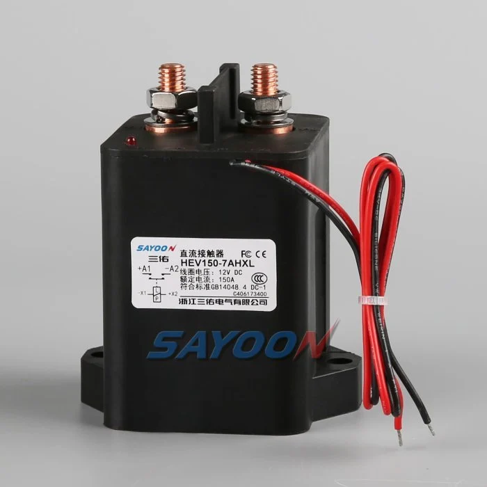
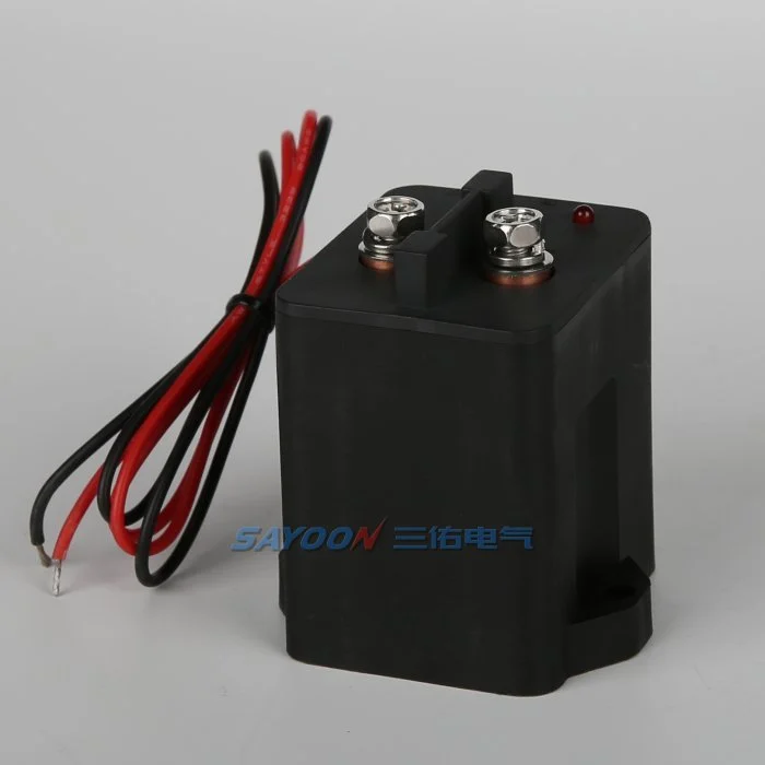
El HEV150 high-voltage sealed DC contactor El que se muestra aquí es una referencia real de un producto Sayoon. Consulte la Gamma de contactores DC de alta tensión Para las clases de corriente adyacentes. La imagen y el nombre de la familia no indican la homologación para un vehículo en particular. La parte final del número, la opción de bobina, el dibujo, la función eléctrica, la protección contra el medio ambiente, la vida útil y la coordinación de protección deben ser revisados conjuntamente.
Mechanical life versus electrical life
Mechanical life describes operations with little or no main-contact current under stated conditions. Electrical life describes operations while making, carrying, or breaking a specified load. In an EV pack, the mechanism may survive far more cycles than the contacts can endure under DC arcing. Use mechanical life to check wear from diagnostic exercises and key cycles, but use electrical-endurance evidence for current-carrying events.
The catalogue value is valid only for its test voltage, current, load type, switching frequency, ambient condition, conductor arrangement, and failure criterion. Do not scale it by current alone or assume that half the rated current automatically doubles life.
Build a mission profile
Estimate vehicle years, operating days, trips per day, charge sessions, service events, diagnostic cycles, and abnormal shutdowns. For each event, record whether the contactor makes current, carries current, or breaks current; the voltage and current at the instant of transition; polarity; duration; temperature; and precharge state. Group similar events into bins rather than using one average cycle.
A simple planning total is N_total = years × operating days per year × events per day, but that number is only the start. A life model must preserve the different wear severity of normal zero-current opening, capacitive make, regenerative current, and emergency interruption.
Estimate wear with duty bins
For each validated duty bin, divide the planned number of events by the demonstrated endurance for that exact or conservatively bounding condition. Summing those fractions can be used as an engineering screening index: D = Σ(nᵢ / Nᵢ). If D approaches one, the planned duty consumes the demonstrated endurance. This is not a universal physical law and should not replace supplier data or qualification testing; it is a traceable way to combine approved test points.
Example inputs should come from measured vehicle traces and manufacturer curves. If no endurance point bounds a severe event, mark the result unavailable and request testing. Never invent an Nᵢ value from a nominal current rating.
Precharge and make-current control
Incorrect precharge can dominate contact wear. An inverter DC link initially appears as a capacitive load, so closing the main contactor before the voltage difference is reduced creates a high make pulse. Verify the resistor value, pulse energy, timeout, and measured voltage ratio. Count failed or repeated precharge attempts because they can create more severe events than normal starts.
A contactor that carries 150 A continuously may still be damaged by a much shorter uncontrolled inrush. Separate carry heating from make erosion in the review. The precharge controller should use measured voltage rather than a fixed delay alone.
Breaking current and arc energy
DC current has no natural zero crossing, so voltage, current, circuit inductance, polarity, arc-control structure, and opening speed influence interruption wear. Normal software should remove torque or charging current before opening when the safety concept permits. Emergency opening must be treated as a separate qualified event with its own limit and expected count.
Do not average one high-current break into hundreds of no-load operations. If a crash device or fuse is intended to clear the severe fault, document the coordination and the residual duty the contactor must survive.
Temperature, resistance and installation
Contact heating is related to current squared times resistance. Ambient temperature, enclosure airflow, terminal torque, busbar support, conductor size, and neighboring heat sources change the contact temperature and therefore the life margin. Record contact resistance and terminal temperature on new samples and after endurance blocks.
A rising voltage drop can indicate wear or a loose connection, but the measurement method must exclude cable and joint resistance. Use consistent four-wire points where practical and define the acceptance limit from approved product data.
Validation and confidence
Run representative duty sequences on production-intent contactors, drivers, busbars, and protection hardware. Include cold and hot starts, supply tolerance, vibration, and the switching waveforms that drive the life model. Inspect timing, contact resistance, temperature rise, insulation, and failure modes at planned intervals. Test multiple samples so one favorable unit is not treated as a population guarantee.
Compare measured wear with the calculation, revise the duty bins, and retain the evidence with the vehicle program. Add margin for uncertainty, manufacturing variation, and foreseeable retries.
RFQ data for a life review
Send the battery voltage range, current traces at make and break, continuous duty, switching frequency, event counts, current direction, DC-link capacitance, precharge sequence, fault-clearing strategy, temperature, vibration, mounting, conductor size, coil driver, and target years. Ask the supplier to identify which endurance data applies and what additional qualification is needed.
The HEV150 shown here is a real product reference. Final life approval requires the exact model, coil option, duty, and installation—not a visual match or headline ampere rating.
Récord de aceptación
Crear un registro controlado que contenga el número de pieza completo, la versión del dibujo, la opción de bobina, las funciones de terminales, el rango de voltaje, la forma de onda de la corriente, el estado de conmutación, los detalles de carga y descarga, el controlador y la supresión, la lógica auxiliar, el estado HVIL, la protección, las temperaturas ambiente y del recinto, la orientación del montaje, los detalles del conductor y de la barra de conexión, las ubicaciones de los instrumentos, el estado de calibración, la versión del software y los límites de aprobación/rechazo. Separar los valores medidos de los valores del catálogo y marcar como evidencia no presente la ausencia de datos como acción abierta en lugar de insertar un valor típico.
Pruebas en los puntos cruciales: suministro de bobinas bajo y alto, condiciones frías y calientes, la correa de seguridad más larga aprobada, ciclos repetidos y el estado anormal mencionado en el concepto de seguridad. Captura de los datos de comando, tensión y corriente de la bobina, retroalimentación auxiliar, tensión del paquete, tensión en el lado de carga y señales de fallo en una base de tiempo única. Detener las repeticiones automáticas después de un desajuste inexplicable, aislar la energía almacenada y preservar la evidencia de fallo inicial. Fotografiar la configuración y el diseño de los terminales, identificar todos los puntos de medición, registrar el cableado y la busbar de intención de producción y explicar por qué cada umbral es seguro. Repetir una muestra representativa después de la estabilización térmica y después del bloque de resistencia previsto. Incluir al operador, la fecha de la prueba, la identidad de la muestra, y cualquier desviación del conjunto de producción. Un ciclo exitoso posterior no debe borrar una falla anterior. Estos registros permiten comparar una muestra de reemplazo, una revisión del proveedor, una actualización del firmware o un cambio de cableado con el mismo nivel de aprobación aprobado.
Guías relacionados de Sayoon
Utiliza el Guía de selección de contactores de CC, flujo de trabajo de prueba segura de contactores, y Guía de horarios de apertura y cierre para decisiones complementarias. feedback plausibility guide explains command, auxiliary, and bus-voltage correlation.
Video educativo
A Look At High-Voltage EV Contactor Technology by CHARGED Electric Vehicles Magazine provides visual background related to this engineering review. It does not replace the written requirements, product data, or vehicle safety procedure.
Mira el video educativo en YouTube.
Preguntas frecuentes
What is the most important check for ev contactor life calculation?
Comienza con la tensión máxima y la forma de cambio real, luego verifica los datos exactos del contactor, la secuencia de control, la instalación y el comportamiento en caso de avería.
¿Puede un contacto auxiliar demostrar que los contactos principales están sanos?
No. El mecanismo de informes de retroalimentación auxiliar se limita a los parámetros de tensión de bus, tiempo de respuesta, corriente de bobina y estado del circuito.
¿Puede utilizarse una clasificación nominal de corriente como norma de selección completa?
No. La corriente continua, la corriente de fuga, la ruptura de corriente, la tensión, la temperatura, la polaridad, la vida útil, la protección contra la sobrecarga y la protección contra sobretemperatura son condiciones independientes.
¿Qué información debe incluirse en una solicitud de oferta?
Envíe formas de onda de voltaje y corriente, secuencia de conmutación, entorno, detalles de bobina y controlador, lógica de retroalimentación, protección, montaje, objetivo de vida útil y evidencia de pruebas requerida.
Referencias autorizadas
- IEC 60947-4-1 contactor and motor-starter standard page
- Texas Instruments high-voltage contactor driver note
- NREL vehicle technologies research
Utilice la edición y los requisitos adoptados por el programa de vehículos. Los estándares y los datos del proveedor pueden cambiar, y el equipo de ingeniería responsable debe confirmar el diseño final.





