Respuesta rápida: An 800V EV contactor must be selected for the battery’s maximum charged voltage and transients, not the nominal architecture label. It must also satisfy insulation coordination, DC make and break duty, bidirectional current, thermal rise, precharge, short-circuit coordination, coil-driver behavior, feedback diagnostics, environmental stress, and the vehicle’s required switching life.
Esta guía técnica convierte el tema en una secuencia fácil de revisar para los equipos de baterías, BMS, pruebas, adquisición de materiales y servicio. Utiliza la familia de productos reales como referencia, manteniendo todas las valoraciones y decisiones de seguridad vinculadas a la aplicación final y a la documentación actual del fabricante.
Mapa de decisiones
| Estado de funcionamiento | Evidencias esperadas | Foco en la ingeniería |
|---|---|---|
| Maximum working voltage | Highest charged pack plus defined operating tolerance | Use model-specific DC ratings and system transients |
| Insulation | Clearance, creepage, dielectric and pollution environment | Coordinate pack, enclosure, altitude and service access |
| Current duty | Traction, regeneration, charging and fault opening | Separate continuous, peak, make and break conditions |
| Protección | Fuse, pyrofuse, precharge and discharge coordination | Prove fault energy and safe isolation sequence |
Referencia del producto y límites de aplicación
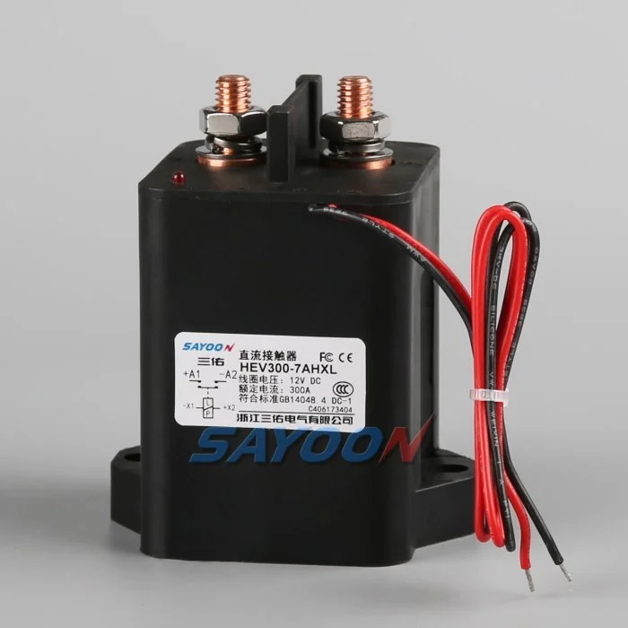
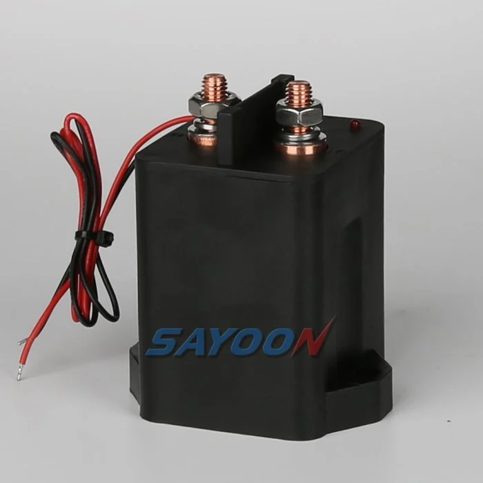
El HEV300 high-voltage sealed DC contactor El que se muestra aquí es una referencia real de un producto Sayoon. Consulte la Gamma de contactores DC de alta tensión Para las clases de corriente adyacentes. La imagen y el nombre de la familia no indican la homologación para un vehículo en particular. La parte final del número, la opción de bobina, el dibujo, la función eléctrica, la protección contra el medio ambiente, la vida útil y la coordinación de protección deben ser revisados conjuntamente.
800V is an architecture class, not one fixed voltage
An “800V” vehicle does not operate at exactly 800 V in every state. The pack voltage changes with cell chemistry, series count, state of charge, temperature, and load. Charging and regeneration can place the pack near its maximum charged voltage, while switching transients can briefly add stress. Specify the minimum, nominal, maximum continuous, and defined transient voltages.
Select the contactor using the manufacturer’s approved DC voltage conditions and insulation data. Do not approve a device merely because its name includes 800 V or because an AC insulation number looks high.
Insulation coordination and altitude
Higher voltage increases the importance of creepage, clearance, dielectric withstand, pollution degree, material group, sealing, and the distance to grounded metal. Altitude reduces air density and can require larger clearances or derating. The completed battery junction box—not the contactor alone—must maintain the required insulation under condensation, contamination, vibration, and service conditions.
Review terminal spacing, busbar geometry, mounting hardware, sensors, connector pins, and enclosure ribs. Use the standards and vehicle requirements adopted by the project; do not copy a spacing number without matching the environment and overvoltage category.
DC interruption at higher voltage
A DC arc does not naturally cross zero. At higher voltage, the contactor’s arc-control system, contact gap, opening speed, magnetic field, gas sealing, and current direction become critical. Continuous current and breaking current are different ratings. Confirm make and break performance at the maximum voltage, actual load inductance, and the required polarity or bidirectional condition.
Normal control should reduce inverter or charger current before opening when safe. Emergency opening, crash isolation, and fault interruption require separately qualified duties and protection coordination.
Thermal current and power relationships
For the same power, higher voltage can reduce current, but that does not automatically make the contactor cooler. Fast charging, launch, regeneration, enclosure temperature, terminal resistance, and busbar design still determine heating. Contact loss is approximately I²R, and joint resistance outside the contactor can become equally important.
Use measured current profiles and thermal boundary conditions. Verify temperature rise at the terminals and body with the production busbar, torque, conductor size, airflow, and neighboring fuse or pyrofuse.
Precharge and discharge
The inverter DC link must be charged through a controlled path before the main contactor closes. At 800V-class levels, the stored energy and make-current consequence are substantial. Size the resistor and precharge contactor for maximum voltage difference, capacitance, pulse energy, repeat duty, and temperature. Close the main contactor only after measured voltages meet the approved ratio and timing window.
After opening, verify that the discharge circuit reduces the load-side bus to the vehicle-defined safe threshold. A timer without voltage confirmation cannot prove the bus is safe.
Bidirectional current and charging compatibility
Traction current flows from the battery to the inverter, while regeneration and DC charging send current toward the battery. Confirm that the main contactor carries and switches the required directions. Some 800V vehicles also interact with lower-voltage chargers through a booster or reconfiguration strategy, which can create additional contactor states and switching sequences.
Map each configuration and prevent two contactors from creating an unintended parallel or series path. Add feedback and bus-voltage plausibility checks for every state.
Short-circuit and crash coordination
Define the prospective pack fault current, battery impedance, cable and busbar inductance, fuse or pyrofuse clearing behavior, and the contactor’s required withstand or interruption duty. The contactor is not a substitute for a fuse, and a fuse does not provide repeatable functional switching. The safety concept should state which device acts first and what energy remains downstream.
After a crash event, inhibit reclose, verify isolation and discharge, and require inspection of the contactor, terminals, busbars, fuse, precharge branch, and trigger circuits before service release.
Coil drive, feedback and EMC
The low-voltage coil driver must provide reliable pull-in during supply sag and controlled release during faults. Suppression changes opening time and driver stress. Capture coil current, command, auxiliary feedback, pack voltage, and load-side voltage on one time base. Use independent voltage evidence to detect welded or stuck-open main contacts.
At 800V-class switching levels, layout, shielding, grounding, and measurement isolation affect EMC and diagnostic accuracy. Validate the production harness and controller, not only a short bench setup.
RFQ and qualification checklist
Provide minimum, nominal, maximum and transient pack voltage; continuous and peak currents; current direction; make and break waveforms; DC-link capacitance; precharge and discharge requirements; short-circuit source; protection clearing time; insulation environment; altitude; temperature; vibration; sealing; coil voltage; driver and suppression; auxiliary logic; life; mounting; busbars; and required approvals.
The HEV300 shown here is a product reference. Confirm the exact voltage, current, insulation, coil, and endurance data for the final model and production installation.
Récord de aceptación
Crear un registro controlado que contenga el número de pieza completo, la versión del dibujo, la opción de bobina, las funciones de terminales, el rango de voltaje, la forma de onda de la corriente, el estado de conmutación, los detalles de carga y descarga, el controlador y la supresión, la lógica auxiliar, el estado HVIL, la protección, las temperaturas ambiente y del recinto, la orientación del montaje, los detalles del conductor y de la barra de conexión, las ubicaciones de los instrumentos, el estado de calibración, la versión del software y los límites de aprobación/rechazo. Separar los valores medidos de los valores del catálogo y marcar como evidencia no presente la ausencia de datos como acción abierta en lugar de insertar un valor típico.
Pruebas en los puntos cruciales: suministro de bobinas bajo y alto, condiciones frías y calientes, la correa de seguridad más larga aprobada, ciclos repetidos y el estado anormal mencionado en el concepto de seguridad. Captura de los datos de comando, tensión y corriente de la bobina, retroalimentación auxiliar, tensión del paquete, tensión en el lado de carga y señales de fallo en una base de tiempo única. Detener las repeticiones automáticas después de un desajuste inexplicable, aislar la energía almacenada y preservar la evidencia de fallo inicial. Fotografiar la configuración y el diseño de los terminales, identificar todos los puntos de medición, registrar el cableado y la busbar de intención de producción y explicar por qué cada umbral es seguro. Repetir una muestra representativa después de la estabilización térmica y después del bloque de resistencia previsto. Incluir al operador, la fecha de la prueba, la identidad de la muestra, y cualquier desviación del conjunto de producción. Un ciclo exitoso posterior no debe borrar una falla anterior. Estos registros permiten comparar una muestra de reemplazo, una revisión del proveedor, una actualización del firmware o un cambio de cableado con el mismo nivel de aprobación aprobado.
Also verify labeling, service documentation, isolation points, and change-control approvals before the production design is released to vehicle assembly.
Guías relacionados de Sayoon
Utiliza el Guía de selección de contactores de CC, flujo de trabajo de prueba segura de contactores, y Guía de horarios de apertura y cierre para decisiones complementarias. feedback plausibility guide explains command, auxiliary, and bus-voltage correlation.
Video educativo
WHAT IS 800-Volt Architecture in EVs? by EV Zone provides visual background related to this engineering review. It does not replace the written requirements, product data, or vehicle safety procedure.
Mira el video educativo en YouTube.
Preguntas frecuentes
What is the most important check for 800v ev contactor?
Comienza con la tensión máxima y la forma de cambio real, luego verifica los datos exactos del contactor, la secuencia de control, la instalación y el comportamiento en caso de avería.
¿Puede un contacto auxiliar demostrar que los contactos principales están sanos?
No. El mecanismo de informes de retroalimentación auxiliar se limita a los parámetros de tensión de bus, tiempo de respuesta, corriente de bobina y estado del circuito.
¿Puede utilizarse una clasificación nominal de corriente como norma de selección completa?
No. La corriente continua, la corriente de fuga, la ruptura de corriente, la tensión, la temperatura, la polaridad, la vida útil, la protección contra la sobrecarga y la protección contra sobretemperatura son condiciones independientes.
¿Qué información debe incluirse en una solicitud de oferta?
Envíe formas de onda de voltaje y corriente, secuencia de conmutación, entorno, detalles de bobina y controlador, lógica de retroalimentación, protección, montaje, objetivo de vida útil y evidencia de pruebas requerida.
Referencias autorizadas
- SAE J1766 electric and hybrid vehicle safety practice
- Texas Instruments, impulsando contactores de alta tensión en vehículos eléctricos y híbridos
- NHTSA electric-vehicle safety information
- Berkeley power electronics technical report
Utilice la edición y los requisitos adoptados por el programa de vehículos. Los estándares y los datos del proveedor pueden cambiar, y el equipo de ingeniería responsable debe confirmar el diseño final.





