Risposta rapida: A battery string contactor connects one battery string to a shared BESS DC bus only after the controller proves compatible voltage, polarity, insulation, precharge, and communications. In parallel racks, it also isolates a faulty or serviced string without allowing the remaining strings to back-feed it. Safe operation depends on coordinated sequencing, current-sharing limits, string fuses, voltage sensing, feedback diagnostics, and controlled discharge.
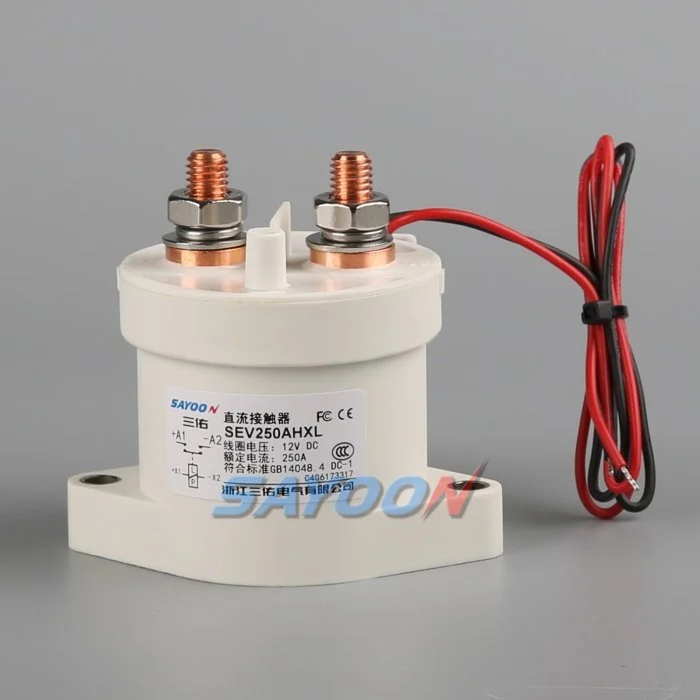
Questa guida trasforma il tema in un flusso di lavoro per la progettazione, la messa in servizio e l’approvvigionamento del BESS, che può essere verificato. Utilizza un vero contattore Sayoon come riferimento visivo del prodotto, mantenendo ogni valutazione, sequenza e decisione relativa alla sicurezza legata al sistema finale e alla documentazione attuale del produttore.
Mappa delle decisioni ingegneristiche
| Stato del sistema | Condizione elettrica prevista | Focus sul design |
|---|---|---|
| String offline | Both mains open; bus may remain live | Prove isolation on both sides |
| Precarica | Precharge path active; mains open | Limit equalization current and verify voltage |
| Parallel online | Mains closed after voltage match | Monitor string current and sharing |
| String fault | Affected string opens; others remain controlled | Coordinate contactor, fuse, PCS, and discharge |
Referenza e ambito del prodotto
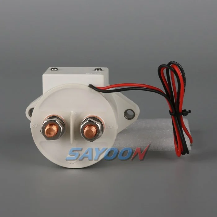
Il SEV250AHXL sealed high-voltage DC contactor è un esempio pertinente di una famiglia di prodotti reali. Guida dei contattori DC ad alta tensione e Guida alla scelta dei contattori in corrente continua per il flusso di lavoro più ampio. Una corrispondenza visiva o un flusso nominale non consentono di considerare un modello adatto per un BESS. Confermate la tensione, il carico corrente, la funzione di apertura e chiusura, la polarità, l’isolamento, la temperatura, l’ambiente, la durata, l’installazione, il driver e la protezione insieme.
Why each string needs a controlled boundary
Parallel battery strings share a bus but do not remain identical. State of charge, temperature, internal resistance, cable resistance, and aging change each string voltage and current. A battery string contactor gives the BMS a controlled boundary for startup, fault containment, maintenance, and availability management. It is not a replacement for the string fuse and cannot correct cell imbalance.
The one-line diagram should show positive and negative mains, precharge branch, fuse, service disconnect, voltage and current sensors, insulation monitoring, auxiliary feedback, and the shared PCS connection. Mark every section that can remain energized when a single string is offline.
Match voltage before paralleling
Closing two strings with different open-circuit voltages can create a large equalization current limited mainly by impedance. Before closure, compare string voltage and bus voltage with sensors that have known accuracy and timing. Confirm polarity and communications. Use precharge or another approved matching method where required.
The acceptance window must include sensor error, contactor timing, capacitance, cable impedance, and the BMS strategy. A fixed delay does not prove voltage match. If the bus is outside the approved window, stop the sequence, identify the energizing source, and prevent repeated closure attempts.
Sequence the contactors and precharge path
A typical sequence verifies interlocks and insulation, closes the designated return path, activates precharge, watches bus voltage rise, closes the main path, then opens or de-energizes the precharge branch as designed. The exact order depends on the system. Document the expected voltage and feedback after every step.
On shutdown, reduce PCS current when possible, open the required mains, confirm current stops, and verify the isolated side. The shared bus can stay energized from other strings, so pack-side and bus-side measurements are both necessary.
Manage current sharing after closure
Once parallel, current does not divide perfectly. A lower-resistance or higher-voltage string can take more charge or discharge current. Monitor each string rather than relying only on total PCS current. Set warning and trip logic from validated battery and conductor limits, including sensor uncertainty and transient sharing.
Investigate persistent imbalance through state of charge, cell temperature, contact resistance, fuse and busbar joints, cable length, sensor calibration, and BMS estimates. Do not repeatedly open and close a string to force sharing unless the approved control strategy specifically supports that behavior.
Isolate faults without creating another fault
A string overcurrent, insulation fault, thermal event, communications loss, or contactor mismatch may require isolation. The controller must decide whether to reduce PCS power first, open the affected string, or shut the common bus. Opening under current must remain within the contactor duty and protection concept.
Other strings can feed the fault through the bus until the isolation and fuse sequence completes. Calculate prospective current and clearing energy. Preserve first-fault timing so the team can distinguish a battery fault from a welded contactor, failed driver, or incorrect current sensor.
Detect welded and stuck-open conditions
Compare contactor command, coil current, auxiliary feedback, string current, string voltage, and bus voltage. A closed auxiliary contact does not prove low-resistance main conduction. An open auxiliary contact does not prove that bus voltage has disappeared. Evaluate the complete circuit, including a parallel back-feed path.
After an open command, a persistent current is strong evidence of an unintended path. Similar voltage on both sides may be normal when the shared bus remains energized and the isolated string voltage is close, so use an approved diagnostic stimulus or discharge path rather than voltage equality alone.
Commission strings one at a time
Commission with production-intent racks, busbars, controllers, sensors, fuses, and PCS. Verify polarity, part numbers, drawings, terminal torque, coil supply, suppression, auxiliary logic, and sensor calibration before energizing. Bring one string online through the complete sequence while recording synchronized waveforms.
Repeat for each physical position, then test parallel connection, controlled removal of one string, communication loss, low control voltage, sensor faults, failed precharge, emergency stop, and restart restrictions. Use authorized procedures for hazardous energy and do not bypass interlocks to accelerate testing.
Document the operating envelope
Record the number of strings, battery voltage range, permissible voltage mismatch, charge and discharge currents, transient sharing, current at make and break, precharge capacitance and resistance, fault current, fuse clearing, temperature, enclosure, conductor resistance, switching cycles, coil driver, feedback, and service strategy.
The SEV250AHXL shown here is a product-family reference. Confirm the final part number and product-specific data for the real string duty. Keep calculations, raw waveforms, settings, deviations, and approvals with the as-built configuration.
Manage changes and periodic checks
Review the original evidence whenever cell chemistry, string count, PCS firmware, cable length, busbar, fuse, cooling, sensor calibration, contactor coil, driver suppression, or operating schedule changes. A physically interchangeable part can alter current sharing, pickup margin, release time, or fault coordination. Identify the affected assumptions and repeat the necessary tests.
During maintenance, inspect terminal joints, barriers, conductors, heat evidence, contamination, mounting, control wiring, and diagnostic history. Compare voltage drop and temperature only under comparable current and measurement conditions. After replacement work, exercise the complete approved sequence under representative load and confirm that one isolated string cannot be energized through the common bus or an auxiliary path. Record the reviewer and final disposition.
Controllo della sicurezza e dei dati
Trattare la batteria, i condensatori comuni, i convertitori, i rack paralleli, i componenti ausiliari e l’attrezzatura di prova come sorgenti di energia pericolose fino a quando una persona autorizzata non avrà applicato la procedura di isolamento del sito e verificato lo stato richiesto con strumenti di misura nominali. Non collegare i pin di feedback, non forzare la bobina, non disattivare gli interblocchi HV e non aprire un dispositivo al di fuori della sua funzione di commutazione prevista. Una BESS può rimanere alimentata in una direzione che non è evidente sulla schematizzazione semplificata.
Definisca i limiti di accettazione in base ai dati esatti del prodotto, ai requisiti del sistema approvati e alle prove rappresentative. Registra il codice completo dell’ordine, la revisione del disegno, l’opzione per i bobini, la mappa dei terminali, l’allineamento dei conduttori, le posizioni degli strumenti, la calibratura, la temperatura, la versione del software, le forme d’onda originali, i criteri di passaggio/non passaggio, le deviazioni e i revisori. Rileva separatamente i fatti misurati dalle interpretazioni. Quando manca una prova, registra un’azione aperta anziché inserire un valore tipico.
Guida tecniche correlate
Usa il Guida alla misura del resistore di precarica, Guida alla plausibilità del feedback dei contattori, Guida alla resistenza al cortocircuito, e Guida alla coordinazione dell'isolamento come controlli complementari. Queste pagine coprono diverse decisioni e dovrebbero essere applicate allo stesso limite di sistema approvato.
Video educativo
Cos'è un contattore e come funziona? Il documento "Electrician U" fornisce informazioni visive sull'utilizzo dei contattori e delle interruttori ad alta tensione. Non sostituisce i requisiti di progettazione scritti né la validazione specifica per il prodotto.
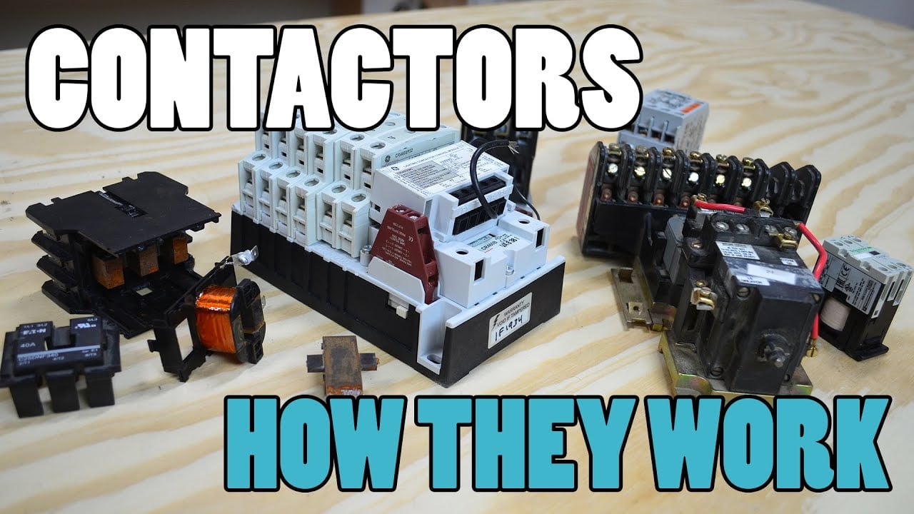
Guarda il video educativo su YouTube.
Domande frequenti
What is the first rule for battery string contactor?
Definisci i limiti del circuito e ogni sorgente che possa alimentare il circuito, quindi verifica la corretta operatività del dispositivo confrontando le onde di tensione e di corrente misurate con i valori specificati.
È possibile verificare tramite il feedback ausiliario che i contatti principali sono ancora attivi?
No. Correlare lo stato ausiliario con la tensione della linea elettrica, la corrente della stringa, la corrente della bobina, il tempo e tutti i possibili percorsi di retroalimentazione.
Devo sostituire un fusibile a striscia con un contattore?
No. Un contattore fornisce l'interruttimento controllato, mentre un fusibile fornisce la protezione contro i cortocircuiti. Le loro funzioni di resistenza e di arresto devono essere coordinate.
Quali dati devono essere inclusi nella richiesta di preventivo per un contattore BESS?
Includete la gamma di voltaggi, le forme d’onda della corrente, i cicli di accensione e spegnimento, la direzione della corrente, la carica preliminare, i correnti di cortocircuito, la protezione, la temperatura, l’installazione, il controllo della bobina, il feedback e l’obiettivo di durata.
Riferimenti autorevoli
- OSHA 1910.147 — Controllo dell’energia pericolosa
- OSHA 1910.333 — Pratiche di lavoro elettrico
- IEC 60947-4-1 — contattori e avviatori di motori
- Dipartimento dell’Energia degli Stati Uniti — stoccaggio dell’energia
Utilizzare le edizioni e i requisiti adottati dal progetto. Le norme e i dati sui prodotti possono cambiare, quindi il team di ingegneri responsabile deve confermare la progettazione finale.





