빠른 답변: An EV contactor life calculation should divide the vehicle duty into distinct switching events, apply the manufacturer’s electrical-endurance data at the actual DC voltage and current, account for temperature, inrush, breaking direction, and fault exposure, and then validate the result with representative testing. Mechanical cycle life cannot be substituted for electrical life because arcing and contact heating dominate when load is switched.
이 엔지니어링 가이드에서는 배터리 팩, BMS, 테스트, 소싱, 서비스 팀을 위한 검토 가능한 순서로 이 주제를 구성합니다. 모든 등급 및 안전 결정은 최종 애플리케이션과 현재 제조사의 문서와 연계하여 이루어지며, 실제 제품군을 참고 자료로 사용합니다.
결정도표
| 운영 상태 | 예상되는 증거 | 엔지니어링 중심 |
|---|---|---|
| Normal key-on/off | Low current after correct precharge and torque removal | Largest cycle count; verify sequence remains controlled |
| Charging connection | Bidirectional current and repeated sessions | Voltage window, current direction, temperature |
| Emergency opening | Higher current or abnormal voltage | Separate qualified duty; do not average into normal cycles |
| No-load diagnostics | Mechanism operates with minimal main current | Counts toward mechanical life, not the same wear per cycle |
제품 참조 및 적용 범위
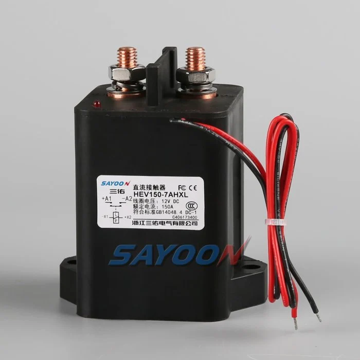
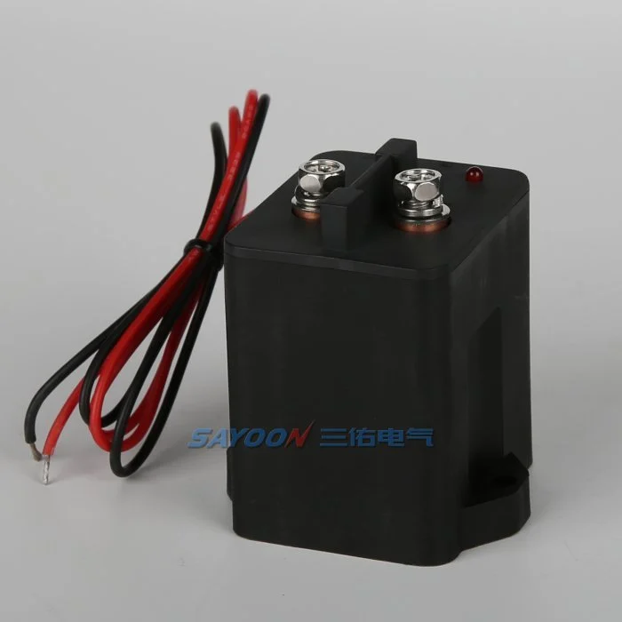
그 HEV150 high-voltage sealed DC contactor 여기서 보여지는 것은 실제 Sayoon 제품의 참조입니다. 검토해 보세요. 고전압 DC 접촉기 범위 접경하는 전류 등급에 적용됩니다. 해당 이미지는 해당 차량에 대한 승인을 의미하지 않습니다. 최종 부품 번호, 코일 옵션, 도면, 전기적 성능, 절연성, 환경 적합성, 수명 및 보호 기능의 조합을 함께 검토해야 합니다.
Mechanical life versus electrical life
Mechanical life describes operations with little or no main-contact current under stated conditions. Electrical life describes operations while making, carrying, or breaking a specified load. In an EV pack, the mechanism may survive far more cycles than the contacts can endure under DC arcing. Use mechanical life to check wear from diagnostic exercises and key cycles, but use electrical-endurance evidence for current-carrying events.
The catalogue value is valid only for its test voltage, current, load type, switching frequency, ambient condition, conductor arrangement, and failure criterion. Do not scale it by current alone or assume that half the rated current automatically doubles life.
Build a mission profile
Estimate vehicle years, operating days, trips per day, charge sessions, service events, diagnostic cycles, and abnormal shutdowns. For each event, record whether the contactor makes current, carries current, or breaks current; the voltage and current at the instant of transition; polarity; duration; temperature; and precharge state. Group similar events into bins rather than using one average cycle.
A simple planning total is N_total = years × operating days per year × events per day, but that number is only the start. A life model must preserve the different wear severity of normal zero-current opening, capacitive make, regenerative current, and emergency interruption.
Estimate wear with duty bins
For each validated duty bin, divide the planned number of events by the demonstrated endurance for that exact or conservatively bounding condition. Summing those fractions can be used as an engineering screening index: D = Σ(nᵢ / Nᵢ). If D approaches one, the planned duty consumes the demonstrated endurance. This is not a universal physical law and should not replace supplier data or qualification testing; it is a traceable way to combine approved test points.
Example inputs should come from measured vehicle traces and manufacturer curves. If no endurance point bounds a severe event, mark the result unavailable and request testing. Never invent an Nᵢ value from a nominal current rating.
Precharge and make-current control
Incorrect precharge can dominate contact wear. An inverter DC link initially appears as a capacitive load, so closing the main contactor before the voltage difference is reduced creates a high make pulse. Verify the resistor value, pulse energy, timeout, and measured voltage ratio. Count failed or repeated precharge attempts because they can create more severe events than normal starts.
A contactor that carries 150 A continuously may still be damaged by a much shorter uncontrolled inrush. Separate carry heating from make erosion in the review. The precharge controller should use measured voltage rather than a fixed delay alone.
Breaking current and arc energy
DC current has no natural zero crossing, so voltage, current, circuit inductance, polarity, arc-control structure, and opening speed influence interruption wear. Normal software should remove torque or charging current before opening when the safety concept permits. Emergency opening must be treated as a separate qualified event with its own limit and expected count.
Do not average one high-current break into hundreds of no-load operations. If a crash device or fuse is intended to clear the severe fault, document the coordination and the residual duty the contactor must survive.
Temperature, resistance and installation
Contact heating is related to current squared times resistance. Ambient temperature, enclosure airflow, terminal torque, busbar support, conductor size, and neighboring heat sources change the contact temperature and therefore the life margin. Record contact resistance and terminal temperature on new samples and after endurance blocks.
A rising voltage drop can indicate wear or a loose connection, but the measurement method must exclude cable and joint resistance. Use consistent four-wire points where practical and define the acceptance limit from approved product data.
Validation and confidence
Run representative duty sequences on production-intent contactors, drivers, busbars, and protection hardware. Include cold and hot starts, supply tolerance, vibration, and the switching waveforms that drive the life model. Inspect timing, contact resistance, temperature rise, insulation, and failure modes at planned intervals. Test multiple samples so one favorable unit is not treated as a population guarantee.
Compare measured wear with the calculation, revise the duty bins, and retain the evidence with the vehicle program. Add margin for uncertainty, manufacturing variation, and foreseeable retries.
RFQ data for a life review
Send the battery voltage range, current traces at make and break, continuous duty, switching frequency, event counts, current direction, DC-link capacitance, precharge sequence, fault-clearing strategy, temperature, vibration, mounting, conductor size, coil driver, and target years. Ask the supplier to identify which endurance data applies and what additional qualification is needed.
The HEV150 shown here is a real product reference. Final life approval requires the exact model, coil option, duty, and installation—not a visual match or headline ampere rating.
수용 기록
완전 부품 번호, 도면 개정 버전, 코일 옵션, 단자 기능, 전압 범위, 전류 파형, 전환 상태, 사전 충전 및 방전 세부 정보, 드라이버 및 억제 기능, 보조 로직, HVIL 상태, 보호 기능, 주변 온도 및 인클로저 온도, 장착 방향, 도체 및 버스바 세부 정보, 계측 장치 위치, 교정 상태, 소프트웨어 버전, 통과/실패 제한값을 포함하는 한 개의 제어된 레코드를 생성합니다. 카탈로그 값과 측정값 간의 차이를 구분하고, 일반적인 값을 삽입하기보다는 누락된 증거를 공개 조치로 표시합니다.
중요한 경계점에서의 테스트: 낮은 및 높은 코일 공급, 찬 및 뜨거운 조건, 가장 긴 승인된 하네스, 반복적인 사이클, 그리고 안전 개념에 명시된 비정상 상태. 한 번의 기준 시간으로 제어 명령, 코일 전압 및 전류, 보조 피드백, 팩 전압, 부하 측 전압, 그리고 결함 경고 신호를 기록합니다. 설명되지 않은 불일치 후 자동 재시도 중지, 저장된 에너지를 분리하고 최초 결함 증거를 보존합니다. 설정 및 단자 배치 사진 촬영, 모든 프로브 지점 식별, 생산 목적의 하네스 및 버스바 기록, 그리고 각 임계값의 안전성을 설명합니다. 열 안정화 후 및 계획된 내구성 블록 후 대표적인 샘플을 반복합니다. 운전사, 시험 날짜, 샘플 식별, 그리고 생산 조립과 동일한 승인된 기준선에 따른 모든 편차를 포함합니다. 이후 성공적인 사이클은 이전 결함이 지워지지 않도록 해야 합니다. 이러한 기록은 교체 샘플, 공급업체 개정, 펌웨어 업데이트, 또는 하네스 변경을 동일한 승인된 기준선과 비교할 수 있도록 합니다.
관련 사이운 가이드
사용하세요 직류(DC) 접촉기 선정 가이드, 안전 접촉기 테스트 워크플로, 그리고 오픈 및 폐업 시간 안내 보완적 결정에 대해서. feedback plausibility guide explains command, auxiliary, and bus-voltage correlation.
교육용 비디오
A Look At High-Voltage EV Contactor Technology by CHARGED Electric Vehicles Magazine provides visual background related to this engineering review. It does not replace the written requirements, product data, or vehicle safety procedure.
자주 묻는 질문
What is the most important check for ev contactor life calculation?
최대 전압과 실제 스위칭 파형을 기준으로 시작하여, 정확한 접점 데이터, 제어 시퀀스, 설치, 그리고 결함 현상을 함께 확인합니다.
보조 연락자가 주요 연락자들의 건강을 입증할 수 있는가?
아니요. 보조 피드백 보고 메커니즘은 한계 내에서 작동합니다. 버스 전압, 타이밍, 코일 전류 및 회로 상태를 독립적인 증거로 사용하십시오.
명목 전류 등급을 완전한 선택 규칙으로 사용할 수 있습니까?
아닙니다. 연속 전류, 전류 흐름, 정지 전류, 전압, 온도, 극성, 수명, 절연성 및 보호 기능의 조화는 별개의 조건입니다.
RFQ와 함께 보내야 하는 정보는 무엇인가요?
전압 및 전류 파형, 스위칭 시퀀스, 환경, 코일 및 드라이버 세부 정보, 피드백 로직, 보호 기능, 장착 방식, 수명 목표 및 필요한 테스트 증거를 보내주십시오.
권위 있는 참고문헌
- IEC 60947-4-1 contactor and motor-starter standard page
- Texas Instruments high-voltage contactor driver note
- NREL vehicle technologies research
차량 프로그램에서 채택한 에디션과 요구 사항을 사용하십시오. 표준 및 공급업체 데이터는 변경될 수 있으며, 책임 있는 엔지니어링 팀은 최종 설계 검증을 수행해야 합니다.





